Dynamic Pressure Balancing Valve Actuator Failures
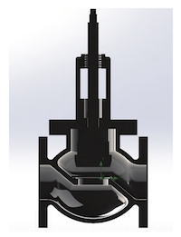
Dynamic pressure-balancing motorized control valves are increasingly used in HVAC hydronic systems and industrial automatic control applications where stable differential pressure and accurate flow regulation are required. These valves combine flow regulation with dynamic pressure compensation, helping maintain relatively consistent design flow even when system differential pressure changes because of pump-speed adjustments, changing loads, or other control actions.
Within this equipment, the electric actuator is the primary electromechanical component responsible for converting an electrical control signal into mechanical valve movement. Its operating condition directly affects valve positioning accuracy, response time, system balancing, and energy performance. A malfunctioning actuator can therefore produce consequences beyond the actuator itself, including unstable room temperatures, excessive pump energy consumption, inadequate terminal-unit flow, control-loop hunting, and unnecessary maintenance.
Unlike a simple two-position actuator, an actuator used with a dynamic pressure balancing control valve may repeatedly move between intermediate positions. It must respond reliably to commands, transmit sufficient torque, accurately determine valve position, and withstand the operating environment over a long service period. Understanding typical actuator problems and their causes is therefore essential for commissioning engineers, HVAC technicians, facility operators, and industrial automation professionals.

A typical automated valve system can be understood as a sequence of interconnected functions:
Controller → Control Signal → Actuator Electronics → Motor → Gear Train → Valve Stem/Shaft → Valve Position → Feedback
The building management system (BMS), DDC controller, PLC, or another automation platform generates a control command. Depending on the system architecture, this may be a modulating analog signal such as 0–10 V or 2–10 V, a digital command, or another approved control protocol.
The actuator interprets the command and energizes its motor in the appropriate direction. The motor produces rotational motion, which is transmitted through gears or another reduction mechanism to generate the required torque. The actuator then moves the valve to the commanded position.
In a closed-loop actuator, a feedback element continuously or periodically reports the actual position. The actuator electronics compare the commanded and actual positions and make corrective adjustments. This feedback function is particularly important where precise flow regulation is required.
A conventional control valve may experience significant changes in flow when system differential pressure changes. Dynamic pressure balancing technology incorporates a mechanism intended to limit or compensate for these effects within its specified operating range.
This allows the valve to maintain more predictable flow as other branches open or close. However, pressure compensation does not eliminate the need for a reliable actuator. The actuator still determines the regulating position, and actuator errors can prevent the valve from operating at its intended point.
A useful way to view the system is that the pressure-balancing mechanism addresses hydraulic variability, while the actuator addresses commanded mechanical positioning. Both must function correctly for the complete valve assembly to deliver stable performance.
One of the first causes to investigate when an electric actuator fails to operate is the power supply. A control signal cannot produce valve movement if the actuator's electrical supply is absent or outside its specified operating range.
Possible causes include:
- Open circuit in the power cable
- Blown fuse or tripped circuit protection
- Loose terminal connection
- Incorrect wiring
- Voltage outside the actuator's specified range
- Short circuit
- Damaged power cable
- Poor electrical contact
- Incorrect transformer capacity in low-voltage systems
A technician should distinguish between loss of power and loss of control signal. These two problems may produce similar symptoms—such as a stationary valve—but require completely different corrective actions.
Voltage that is consistently too low may prevent the motor from generating sufficient torque. Excessively high voltage, depending on actuator design, can overstress electronic components and motor windings.
Transient voltage disturbances can also damage sensitive control electronics. Industrial and commercial HVAC systems may experience electrical disturbances caused by large motors, variable-frequency drives, switching equipment, or inadequate power-quality management.
Therefore, measuring the actual voltage at the actuator terminals during operation is more reliable than simply assuming that the nominal supply is available.
The electric motor converts electrical energy into mechanical torque. Internal winding faults can therefore disable the actuator even when external wiring appears normal.
Typical motor faults include:
- Open winding
- Inter-turn short circuit
- Winding-to-ground fault
- Insulation degradation
- Excessive winding temperature
- Mechanical bearing problems
Electrical testing should be performed according to the manufacturer's maintenance procedure and the motor's design. Resistance measurements, insulation checks, current measurements, and comparative phase testing where applicable can help distinguish electrical from mechanical problems.
An actuator may overheat when the motor repeatedly operates near or beyond its intended load. High torque demand can result from excessive valve friction, a jammed valve, incorrect actuator sizing, or mechanical obstruction.
Continuous cycling can also increase thermal loading. Some actuators are designed for specific duty cycles rather than uninterrupted operation. If the actual control sequence causes significantly more movement than anticipated, the motor may accumulate heat faster than it can dissipate it.
The operating environment also affects actuator temperature. Dust accumulation, restricted ventilation, direct external heat sources, high ambient temperature, or damaged cooling components can reduce heat dissipation.
In HVAC plant rooms and industrial facilities, actuators may be installed near pumps, boilers, heat exchangers, steam lines, or other heat-generating equipment. If the surrounding temperature approaches or exceeds the actuator's rated limit, electronic and mechanical components can age more rapidly.
A basic thermal inspection can therefore provide valuable information. Unusual surface temperature, thermal cycling, discoloration, or repeated thermal protection trips should not be dismissed as normal behavior.
Electric actuators generally use a reduction mechanism because the motor operates at a relatively high rotational speed while the valve requires lower speed and higher torque. The gear train converts motor rotation into controlled valve movement.
As operating hours accumulate, gears can experience wear, surface fatigue, lubrication deterioration, tooth damage, or misalignment.
The symptoms may include:
- Increased operating noise
- Intermittent movement
- Jerky valve travel
- Backlash
- Incomplete stroke
- Positioning errors
- Motor operation without corresponding valve movement
- Mechanical jamming
Because the gear train is located inside the actuator housing, external inspection may not immediately reveal the problem.
Backlash is particularly important for modulating applications. If excessive clearance develops between gear teeth, the motor may rotate slightly without producing the expected valve movement.
For a simple open/close application, a small amount of backlash may be tolerable. For precise modulation, however, it can create a significant difference between commanded position and actual valve position.
This can lead to control instability, especially when the controller continually attempts to correct a position error.
Lubricant degradation can increase friction and operating torque. Conversely, unsuitable lubricant can damage certain materials or perform poorly at the actuator's operating temperature.
Maintenance personnel should therefore use only lubricants and servicing procedures approved by the actuator manufacturer. Introducing an inappropriate lubricant into a precision transmission can create more problems than it solves.
Modern actuators contain electronic circuits for signal processing, motor control, limit management, communication, and feedback. Components such as capacitors, integrated circuits, relays, voltage regulators, and protection devices may degrade with time.
Heat is a major contributor to electronic aging. Repeated temperature cycling can also create mechanical stress in solder joints and electronic connections.
A controller may therefore continue sending a correct signal while the actuator fails to interpret or execute it properly.
Signal transmission is another common failure point. A broken conductor, loose terminal, short circuit, grounding problem, or electromagnetic interference can distort the command received by the actuator.
For analog signals, engineers should verify the actual signal level at the actuator input rather than measuring only at the controller output.
For example, if a controller sends a modulating signal corresponding to a desired intermediate position but the actuator receives an incorrect value because of a wiring fault, the valve may stabilize at the wrong position.
Long signal cables routed near high-power equipment can be susceptible to electromagnetic interference. Variable-frequency drives, large motors, contactors, and switching devices can generate electrical noise.
Appropriate cable selection, grounding, shielding, routing, and installation practices can reduce these problems. The exact requirements depend on the actuator and control-system design.
Some electric actuators use potentiometers to provide position feedback. Mechanical wear can gradually change the resistance characteristics of the potentiometer, resulting in unstable or inaccurate position information.
Typical symptoms include:
- Position indication jumping
- Inconsistent feedback
- Incorrect displayed valve position
- Control-loop oscillation
- Failure to reach the expected position
Because potentiometers are mechanical components, their service life depends on travel frequency, environmental conditions, and construction quality.
More advanced actuators may use optical, magnetic, or other encoder technologies. Encoders can provide more precise position information, but they remain dependent on correct electrical connections, sensor integrity, and electronic processing.
A failed encoder can cause the actuator to lose its reference to actual valve position. Depending on the control architecture, the actuator may stop, enter a protective mode, move to a predefined position, or report a fault.
The feedback device itself may be healthy while its signal cable is damaged. Cable breaks, connector oxidation, loose terminals, and insulation problems can all interrupt feedback.
This is why troubleshooting should follow the entire feedback path rather than immediately replacing the sensor.
Actuator housings are normally protected by seals, gaskets, or other enclosure features designed to prevent the entry of water, dust, and contaminants.
Over time, sealing materials can harden, crack, deform, or lose elasticity. Once protection deteriorates, the actuator's internal environment can become progressively more hostile.
Water entering an actuator can cause corrosion of metal components and potentially create electrical leakage or short circuits. Condensation may also occur when equipment experiences significant temperature changes.
This is particularly relevant in HVAC environments where humidity and condensation can be present around chilled-water systems.
The problem can develop gradually. An actuator may initially continue operating despite minor moisture ingress, but corrosion of connectors, circuit boards, bearings, or gears can eventually produce intermittent or permanent failure.
Dust can accumulate around moving components and ventilation surfaces. In industrial environments, contaminants may include metal particles, process dust, chemical aerosols, or other materials.
Contamination can increase mechanical friction and reduce heat dissipation. Therefore, enclosure integrity and appropriate environmental protection should be considered during both initial selection and long-term maintenance.
Not every actuator failure originates inside the actuator. The valve itself may develop increased operating torque because of scale, corrosion, deposits, damaged seals, excessive packing friction, or internal mechanical deformation.
If the actuator is repeatedly asked to overcome excessive resistance, the motor and transmission can become overloaded.
This distinction is essential during troubleshooting. Replacing an actuator without identifying the underlying valve problem may result in another actuator failing shortly afterward.
An undersized actuator may operate close to its maximum torque capacity during normal conditions. Such a configuration can cause overheating, slow movement, thermal protection activation, and premature mechanical wear.
An oversized actuator is not necessarily ideal either. Excessive actuator force or torque can place unnecessary mechanical stress on the valve stem, shaft, seat, or other components.
Proper sizing should consider the actual valve torque or thrust requirements, differential pressure, temperature, valve construction, and applicable safety margin.
A dynamic pressure balancing control valve is part of a larger hydronic or industrial control loop. The actuator may appear faulty when the actual problem is an unstable control strategy.
If the controller reacts too aggressively to small changes in differential pressure or temperature, the valve may repeatedly open and close. This is commonly known as hunting or oscillation.
Frequent cycling increases actuator wear and can also destabilize the hydraulic system.
Potential causes include:
- Incorrect controller tuning
- Excessively short control cycles
- Poor sensor location
- Incorrect sensor calibration
- Excessive valve authority
- Incorrect valve characteristic
- Inappropriate control range
- Hydraulic interaction between branches
- Excessive system pressure variation
Therefore, actuator diagnostics should not be performed in isolation. Engineers should examine the entire control loop whenever repeated actuator movement occurs.
| Symptom | Possible Causes | Recommended Investigation |
|---|---|---|
| Actuator does not move | Power failure, motor fault, wiring issue | Check supply and motor circuit |
| Motor runs but valve does not move | Gear damage, coupling failure | Inspect transmission |
| Valve moves slowly | Low voltage, overload, friction | Check supply and valve torque |
| Excessive noise | Gear wear, misalignment, bearing issue | Inspect mechanical transmission |
| Position is inaccurate | Feedback fault, backlash, calibration error | Check sensor and calibration |
| Valve repeatedly hunts | Control tuning, feedback error | Analyze complete control loop |
| Actuator overheats | Excessive load, high cycling, poor cooling | Check duty cycle and torque |
| Intermittent operation | Loose wiring, electronics, moisture | Inspect connections and enclosure |
| Feedback disappears | Sensor or cable failure | Test feedback circuit |
| Corrosion inside housing | Seal failure, moisture ingress | Inspect enclosure and sealing |
Before opening the actuator, record what is actually happening. Determine whether the actuator is completely inactive, moving intermittently, moving in the wrong direction, stopping before full travel, or operating normally but producing unstable process control.
This initial classification prevents unnecessary component replacement.
Measure the actual supply at the actuator terminals under relevant operating conditions. Verify circuit protection, wiring continuity, terminal tightness, and polarity where applicable.
Do not assume that a correct controller display proves that the actuator is receiving the correct power.
Measure the command signal at both the controller and actuator ends where practical. A discrepancy can identify cable or connection problems.
The expected signal range must be checked against the specific actuator specification because different products may use different signal standards.
If the electrical system is functioning, determine whether the valve can move freely within its specified operating range. Mechanical inspection should consider the valve stem, shaft, linkage, coupling, and actuator mounting.
Excessive resistance may indicate a valve problem rather than an actuator-electronics problem.
Compare commanded position with actual valve position and feedback value. If the actuator reaches a physical position but the control system reports an incorrect position, investigate the feedback system.
Check temperature, humidity, dust, condensation, water exposure, vibration, and enclosure condition. Environmental factors often explain intermittent problems that cannot be reproduced under controlled conditions.
Electrical maintenance should include periodic inspection of supply cables, terminals, control wiring, grounding, and protective devices. Loose connections should be corrected before they produce heat or intermittent signal problems.
Where appropriate, operating current and voltage trends can also provide early indications of increased mechanical load.
Maintenance personnel should monitor actuator noise, travel smoothness, response time, and unusual vibration. Any progressive change should be recorded rather than treated as an isolated event.
For equipment with accessible mechanical components, inspection should follow the manufacturer's recommended intervals and procedures.
Position feedback should be verified periodically, especially after actuator replacement, valve maintenance, mechanical adjustment, or control-system modification.
Incorrect calibration can cause a perfectly functional actuator to behave as though it has a mechanical defect.
The actuator's enclosure and cable-entry points should remain intact. Seals, gaskets, glands, and covers should be inspected where applicable.
For HVAC systems, special attention should be given to condensation and chilled-water environments. For industrial plants, chemical exposure, dust, vibration, and high ambient temperature may require additional protection.
Traditional maintenance often relies on fixed inspection intervals. A more advanced approach uses operating data to identify deterioration before failure.
Smart actuators and modern building automation systems can potentially provide information such as valve position, travel time, operating cycles, actuator load, fault codes, and control trends.
By analyzing changes over time, maintenance personnel may identify patterns such as increasing travel time, increasing motor current, excessive cycling, or growing position deviation.
A predictive maintenance strategy can therefore follow a sequence such as:
Normal Baseline → Trend Monitoring → Anomaly Detection → Targeted Inspection → Preventive Intervention
This approach can reduce unnecessary component replacement while increasing the likelihood that developing failures are identified before they interrupt system operation.
The reliability of a dynamic pressure balancing motorized control valve begins before installation. Actuator selection should consider the complete operating environment rather than only nominal valve size.
Important factors include:
- Required torque or thrust
- Valve travel
- Control signal
- Operating frequency
- Duty cycle
- Response time
- Power supply
- Ambient temperature
- Enclosure protection
- Fail-safe requirements
- Manual override requirements
- Feedback method
- Communication protocol
- Maintenance accessibility
The actuator and valve should be treated as an integrated assembly. The correct combination provides sufficient mechanical capacity without unnecessary oversizing while ensuring that the control response matches the process requirement.
Typical failures of electric actuators used with dynamic pressure balancing control valves rarely have a single universal cause. Electrical supply problems, motor winding faults, overheating, gear wear, electronic failures, feedback errors, seal degradation, environmental contamination, excessive valve torque, and control-loop instability can all produce similar symptoms.
Effective troubleshooting therefore requires a systematic approach that separates power, signal, electronics, mechanical transmission, feedback, valve resistance, and control-system behavior. Replacing an actuator without identifying the actual failure mechanism may temporarily restore operation but does not necessarily eliminate the underlying problem.
For HVAC and industrial automation systems, long-term reliability depends on correct actuator sizing, appropriate installation, stable power and signal transmission, environmental protection, regular inspection, feedback calibration, and condition-based maintenance. When these elements are managed together, dynamic pressure balancing motorized control valves can provide more stable flow regulation, better hydraulic performance, improved energy efficiency, and more dependable automated operation throughout their service life.