Root Cause Analysis of Cracking in Welded Flange Globe Valve Bodies
Abstract: This study investigates suspected crack defects in the valve body of a welded flange globe valve used in a process station. The root causes of cracking were analyzed through chemical composition testing, Brinell hardness measurements, metallographic examination, scanning electron microscopy (SEM), and energy-dispersive spectroscopy (EDS). Results indicate that the valve body’s chemical composition and hardness meet standard requirements. However, the primary cause of early cracking is the propagation of forging fold defects under assembly-induced constraint stress. To prevent similar failures, it is recommended to thoroughly remove oxide scale and surface defects from the forging blank during the manufacturing process. Additionally, 100% non-destructive testing (NDT) of both internal and external surfaces should be performed to verify the structural integrity of the valve body.
Instrument valves and pipe fittings typically refer to components with smaller nominal diameters that are widely used in industrial control systems. Among these, the welded flange globe valve is a common type of instrument valve frequently installed in process pipelines.
As a primary valve—often called a "root valve"—it connects directly to process equipment or pipelines. Secondary valves are then attached to these primary valves to complete the system. Instrument fittings are essential components in automatic control systems across industries such as oil refining, chemical processing, petroleum, food production, pharmaceuticals, and instrumentation, valued for their reliable control performance. Cracks in metal materials are fractures that can be either microscopic or macroscopic, occurring during material failure. Based on the fracture mechanism, these cracks can be classified as follows:
- Transgranular Cracks: Cracks that propagate through the metal grains themselves, commonly occurring during fractures at or near room temperature.
- Intergranular Cracks: Cracks that follow the grain boundaries of the metal, often indicating brittle fracture behavior and reduced material toughness.
A welded flange globe valve was installed at an oilfield station, where a suspected crack defect was detected on the valve body during installation. Subsequent dye penetrant testing revealed multiple linear surface defects on several valve bodies. On-site personnel polished one defect, and when the grinding depth reached 30 mm, a follow-up penetrant test was performed. The results showed that the linear defect remained clearly visible, as illustrated in Figure 1. The welded flange globe valve has welding ends measuring 19.05 mm (3/4 inch) and 12.07 mm (1/2 inch), featuring a PN150 flange rated for Class 900 pressure. The valve body is integrally forged as a single piece, incorporating a welded saddle-type nozzle and a branch pipe platform. It functions as a single shut-off valve. The valve body is manufactured from ASME A350 LF2 Class 1 steel, with internal components fabricated from 316 stainless steel. The sealing packing uses flexible graphite for reliable sealing performance. The valve has an irregular shape, as shown in Figure 2, comprising a valve body and a needle valve assembly. Key components include the needle valve handle, valve stem, locking nut, packing bolt, cylindrical pin, and other related parts.
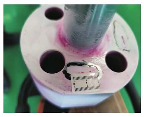
Figure 1. Macroscopic View of Linear Defects on the Valve Body
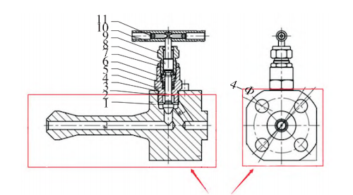
Figure 2. Schematic Diagram of the Welded Flange globe valve
- Valve body
- Lower valve stem
- Valve bonnet
- Packing pad
- Packing
- Material bolt
- Locking nut
- Upper valve stem
- Gland
- Handle
- Cylindrical pin
Figure 3 shows a macroscopic view of the welded flange globe valve body. To the naked eye, the valve body surface appears bright, reflecting its machining and electroplating finish. No abnormal surface corrosion was observed. However, traces of white and red markings appeared in some areas, as shown in Figure 3(a). These marks resulted from residual developer and penetrant used during on-site dye penetrant testing. Machining marks were clearly visible on the valve body flange surface, as shown in Figure 3(b). Defect analysis was performed on one valve body, where surface cracks were identified and measured. A total of six cracks were detected, all concentrated along the welded side of the valve body flange and oriented circumferentially. The longest crack measured approximately 25 mm. Detailed crack measurements are listed in Table 1.
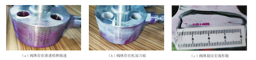
Figure 3 Welded globe valves
(a): Surface traces from penetration testing Figure 3(b): Visible machining marks on the flange surface Figure 3(c): Macroscopic view of valve body cracks
Table 1. Measurement Results of Valve Body Cracks
No. | Crack 1 | Crack 2 | Crack 3 | Crack 4 | Crack 5 | Crack 6 |
Valve Body 1 | 15 mm, circumferential direction, flange welding side | 20 mm, circumferential direction, flange welding side | 25 mm, circumferential direction, flange welding side | 25 mm, diameter direction, handle side | 8.6 mm, circumferential direction, flange welding side | 17.5 mm, circumferential direction, flange welding side |
To evaluate the material quality, samples were taken from the defective valve body for chemical composition analysis. Testing was performed using an ARL 4460 direct-reading spectrometer in accordance with the ASTM A751-21 standard. The results are summarized in Table 2. As shown in Table 2, the valve body’s chemical composition meets the specifications outlined in ASTM A350 LF2 Class 1, confirming full material compliance.
Table 2. Chemical Composition of Valve Body
Element | C | Si | Mn | P | S | Cr | Mo | Ni | Nb | V | Cu |
Result | 0.17 | 0.23 | 0.92 | 0.022 | 0.0016 | 0.031 | 0.0017 | 0.011 | ≤0.0001 | 0.0023 | 0.013 |
Spec. | ≤0.30 | 0.15–0.30 | 0.60–1.35 | ≤0.035 | ≤0.040 | ≤0.30 | ≤0.12 | ≤0.4 | ≤0.02 | ≤0.08 | ≤0.4 |
A cross-sectional specimen was taken from the welded flange globe valve body for hardness testing. The Brinell hardness test was performed using a BH3000 tester following the ASTM A370-22 standard. The measured hardness of 175 HBW meets the requirements of ASTM A350.
The metallographic structure and penetrant test trace defects of the welded flange globe valve body were examined, as illustrated in Figure 4. A vertical cross-section was taken along the linear penetrant test trace on the flange surface. Two metallographic specimens were extracted from this section for detailed analysis. The cross-sections were polished and etched using a 2% nitric acid alcohol solution. Observations were conducted with an OLS 4100 laser confocal microscope in accordance with the GB/T 226-2015 standard. Figures 4(a) and 4(b) show densely distributed small cracks along the edge and near the shallow surface of Specimen No. 1. Figure 4(d) illustrates a crack originating at the surface and extending inward at an angle. The main crack is relatively wide and accompanied by multiple secondary cracks along its edges. The crack tip is blunt. The surrounding microstructure comprises ferrite, pearlite, and a small amount of bainite. Obvious decarburization is present on both sides of the crack. The main crack measures approximately 1.66 mm in length and extends about 1.22 mm deep along the flange wall thickness. Specimen No. 2, shown in Figure 4(e), features a long transverse crack with a rounded, blunt tip. The crack measures approximately 1.61 mm in length and 1.17 mm in depth. Further analysis revealed a grayish embedded substance within the crack gap and the adjacent matrix, as shown in Figure 4(f). A distinct decarburization zone, labeled B-0, was also observed on both sides of the crack and in the surrounding microstructure.
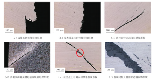
Figure 4. Metallographic Structure and Penetration Defect Analysis of the Valve Body
(a) Crack morphology at the root of the edge burr
(b) Diffuse cracks in the shallow surface matrix
(c) Long crack propagation trend on the flange surface
(d) Decarburization morphology on both sides of the long crack (scale: 100 μm)
(e) Transverse crack penetrating the flange side
(f) Crack gap and gray embedded substance in the matrix (scale: 20 μm)
2.5 Scanning Electron Microscope (SEM) and Energy Dispersive Spectroscopy (EDS) Analysis of the Defective Valve Body
A scanning electron microscope (SEM) sample was extracted from the defective region of the welded flange globe valve body, specifically targeting an area showing visible penetrant test traces. The defect morphology was examined using a VEGA I scanning electron microscope (SEM) and analyzed with an INCA 360 energy-dispersive spectroscopy (EDS) system, as illustrated in Figures 5 and 6. Under SEM observation, parallel machining plow marks were clearly visible beneath the galvanized layer on the flange surface. On the right side of the flange—near the bolt hole where the valve connects—a crack was observed, covered by a substantial amount of lumpy deposits. The crack segment near the bolt hole runs roughly parallel to the machining marks; however, no clear correlation exists between the crack propagation direction and the orientation of the plow marks. The crack widens as it approaches the bolt hole, with smooth and rounded transitions between the crack edges and the surrounding base material, lacking any sharp protrusions. Away from the hole, the crack gradually narrows. EDS analysis was conducted on both the material covering the crack gap and the exposed crack surfaces. The results revealed the presence of oxygen (O), iron (Fe), zinc (Zn), and other elements. The second crack located to the right of the bolt hole, along with two additional cracks on the left side, display similar directional and morphological features as the first crack on the right. All these cracks connect to the flange bolt hole, indicating a shared stress concentration origin.
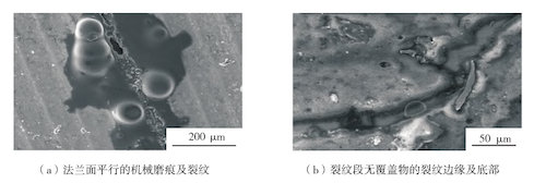
Figure 5. SEM Images of Valve Body Surface and Crack Defects
(a) Mechanical wear marks and surface cracks parallel to machining lines
(b) Morphology of lumpy deposits within the crack gap
(c) Morphology of exposed crack bottom without deposits
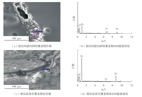
Figure 6. EDS Energy Spectrum Analysis of Crack Regions
(a) EDS spectrum of lumpy deposits inside the crack
(b) EDS spectrum of exposed crack bottom
The analysis confirms that the valve body material’s chemical composition and Brinell hardness meet the requirements for LF2 Class 1 forgings as specified in the ASTM A350/A350M standard. Therefore, the cracks observed in the valve body are not attributed to material quality issues. The base metal microstructure is composed of ferrite, pearlite, and a small amount of bainite. The cracks originate at the surface and propagate inward at an oblique angle. These primary cracks are accompanied by multiple secondary cracks, with the crack tips appearing rounded and blunt—indicative of limited plastic deformation. A distinct decarburization zone is observed on both sides of the cracks. Microscopic analysis revealed diffuse inclusions of various sizes distributed along the crack edges and tips. EDS (energy-dispersive spectroscopy) analysis revealed the presence of loose oxide inclusions—primarily composed of oxygen (O), iron (Fe), and zinc (Zn)—within the crack regions. Additionally, large iron oxide clusters were identified in the base material near the cracks—some directly linked to the cracks, while others were unrelated. This indicates that the iron oxides originated from the parent material and are distributed along grain boundaries. Further examination of the fracture surface—sectioned along the crack propagation path—revealed features indicative of high-temperature melting, including shrinkage cavities in the crack initiation zone. The fracture surface displayed free dendrites and fine shrinkage cavities, with no evidence of plastic deformation. Near the inner surface, a semi-molten dendritic structure was observed, indicating localized overheating during formation. These characteristics are typical of forging fold defects. Such defects form when oxidized surface layers are folded into the deforming metal flow during the forging process. Folding defects are typically caused by sharp corners, fins, depressions, or surface irregularities—such as pores, scratches, or scars—formed during earlier processing stages. These features oxidize more rapidly than the surrounding metal, creating oxide scale that does not fuse with the base material during forging, resulting in fold formation. If oxide scale or surface defects on the raw forging blank are not properly removed, they can become embedded into the metal during rolling or forging. This disrupts the metal’s continuity, ultimately causing internal folding defects that compromise the structural integrity of the valve body.
The chemical composition and hardness of the valve body material meet the specifications of ASTM A350/A350M LF2 Class 1 forgings. The primary cause of early cracking in the valve body is attributed to forging fold defects.
It is recommended to:
- Enhance quality control of forging blanks to ensure complete removal of oxide scale and surface defects.
- Perform 100% non-destructive testing (NDT) on both internal and external surfaces of the valve body to prevent defective valves from being installed in the field.