Impact of Bonnet Flange Thickness on Control Valve Strength: A Finite Element Study
Jul 09, 2025
Abstract: This study analyzes the effect of flange thickness on control valve bonnet strength using finite element analysis, comparing stress distributions in one-piece and split bonnet designs. The results show that, under equal flange thickness, the one-piece bonnet experiences higher stress in regions subjected only to internal pressure, but significantly lower stress in areas affected solely by bolt preload compared to the split bonnet design. As the flange thickness increases, stress levels in both bonnet structures decrease consistently across all regions. These results offer important insights for optimizing bonnet flange design to improve structural integrity and ensure the safe operation of control valves.
With the rapid development of industries such as petroleum, chemical processing, power generation, nuclear energy, metallurgy, pharmaceuticals, and food manufacturing, the demand for high-performance control valves has increased significantly. Among these components, control valves play a vital role in process control systems, directly influencing operational efficiency, system stability, and safety. Depending on the industry and specific application, control valves are available in various designs, and even the bonnet structures of the same valve type can differ between manufacturers. The bonnet is a critical pressure-retaining component of a control valve, designed to withstand internal fluid pressure, mechanical impact, bolt preload, and the output force from the actuator.Therefore, the flange thickness and structural integrity of the bonnet have a direct impact on the reliability of the valve’s pressure boundary. Excessive stress under operating conditions can result in flange leakage, leading to production downtime, safety risks, or even complete system shutdowns. As a result, precise stress analysis and optimized flange design are critical to ensuring the structural integrity, operational safety, and long-term performance of control valves. This study analyzes six design schemes—featuring both one-piece and split bonnet structures with varying flange thicknesses—using finite element modeling to evaluate stress distribution and structural performance. By comparing stress distribution patterns across various bonnet configurations, this study clarifies the influence of flange thickness on bonnet strength, providing valuable insights to support safer and more efficient control valve design.
This study focuses on two commonly used control valve bonnet designs: the one-piece structure and the split structure. The split structure consists of two distinct components—the flange and the inner bonnet—as shown in Figures 1 and 2. The bonnet is fastened to the valve body with ten M42 bolts, and the flange connection features a spiral-wound Inconel 718 gasket, providing reliable high-pressure sealing performance.
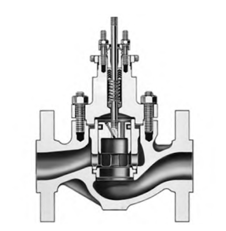
Figure 1: Schematic Diagram of the One-Piece Control Valve Bonnet Structure
Figure 2: Schematic Diagram of the Split Control Valve Bonnet Structure
Both the one-piece and split bonnet structures were modeled in 3D using CREO CAD software to precisely replicate the valve bonnet geometry, as shown in Figures 3 and 4. To analyze the influence of flange thickness on bonnet strength, six models were created—three flange thicknesses (6 cm, 7 cm, and 8 cm) for each bonnet structure. To optimize computational efficiency, the models were simplified by exploiting structural symmetry. Each finite element model was reduced to a 1/20 sector—a fan-shaped segment containing half of a bolt—effectively capturing critical stress zones while significantly reducing simulation time.
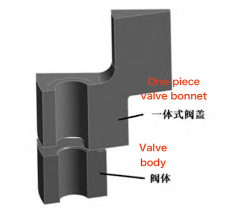
Figure 3: Finite Element Model Showing the One-Piece Control Valve Bonnet Structure
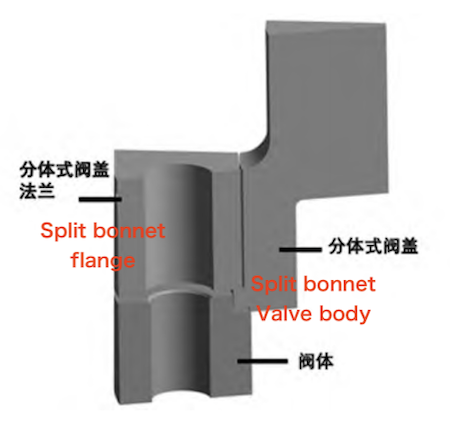
Figure 4: Finite Element Model Showing the Split Control Valve Bonnet Structure
Finite element analysis was conducted using ANSYS, a leading engineering simulation software widely used for structural and stress analysis. Both the one-piece and split bonnet structures of control valves were modeled, simulated, and evaluated in this study. Mesh quality is a crucial factor in numerical simulations, directly impacting the accuracy and stability of the results. The mesh was generated using ANSYS’s Mesh module, employing predominantly hexahedral elements tailored to the geometry and loading conditions of the valve bonnet. The one-piece bonnet model mesh comprises up to 36,119 elements and 143,081 nodes, while the split bonnet model, featuring a more complex geometry, is meshed with up to 57,680 elements and 215,394 nodes.
The valve bonnet material analyzed is CF8M, a cast austenitic stainless steel commonly used for pressure-containing components. Its key mechanical properties are as follows:
- Density: 7,750 kg/m³
- Elastic Modulus: 195 GPa
- Poisson’s Ratio: 0.3
To simulate real operating conditions, a uniform internal pressure was applied to the inner surface of the valve bonnet. The valve is designed to meet ASME Class 600 standards, operating at a pressure of 24.82 MPa and a temperature of 21 °C, with room-temperature water as the working medium. To ensure effective sealing between the spiral wound gasket and the flange under pressure, a preload force of 157,890 N—equivalent to half of the bolt’s total preload—was applied at the bolt locations. Two boundary conditions were applied to the finite element model: frictionless support constraints were assigned to the symmetry surfaces to simulate model symmetry and reduce computational effort without compromising accuracy. The bottom surface, representing part of the valve body, was assigned a compression-only support to restrict displacement while allowing realistic stress distribution.
This study analyzes the equivalent stress distribution under varying flange thicknesses for both one-piece and split bonnet structures. Stress contour maps for the one-piece bonnet are presented in Figure 5, while those for the split bonnet are shown in Figure 6. The analysis focuses on:
- S1 represents the critical path in the bonnet area subjected solely to internal medium pressure.
- S2 represents the critical path in the bonnet area subjected solely to bolt preload.
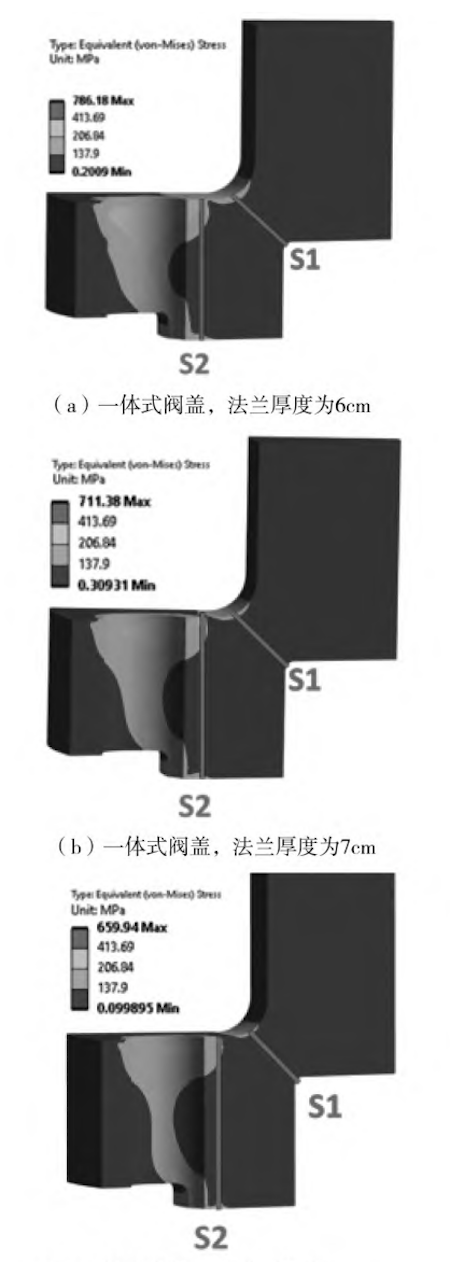
Figure 5: Equivalent stress distribution in one-piece bonnets with flange thicknesses of (a) 6 cm, (b) 7 cm, and (c) 8 cm

Figure 6: Equivalent stress distribution in split bonnets with flange thicknesses of (a) 6 cm, (b) 7 cm, and (c) 8 cm
From Figures 5 and 6, it can be observed that in the split bonnet design, the stress in the S1 region is significantly lower than in the S2 region. This indicates that the S2 area is the weakest point of the split bonnet and plays a critical role in determining its overall structural integrity.
In contrast, the one-piece bonnet exhibits similar stress levels in both the S1 and S2 areas, so the weakest region depends on the relative stress values along these paths.
The stress values along the 12 critical paths (S1 and S2 for each flange thickness in both bonnet structures) are summarized in Table 1 and illustrated in Figure 7.
Key Findings: Effect of Flange Thickness on the S1 Region (Medium Pressure Only)
- As flange thickness increases, stress decreases in both one-piece and split bonnet designs.
- The one-piece bonnet shows a modest stress reduction of about 13%.
- The split bonnet experiences a more significant stress reduction of approximately 20%.
- At the same flange thickness, the one-piece bonnet exhibits over 23% higher stress than the split bonnet in the S1 region.
- Despite these differences, all S1 stress values remain well below the allowable stress limit of 137.9 MPa.
Effect of Flange Thickness on the S2 Region (Bolt Preload Only)
- Stress decreases as flange thickness increases in both bonnet designs.
- The one-piece bonnet exhibits only a 3% change, indicating greater stress stability.
- The split bonnet experiences a significant stress reduction of approximately 20%.
- At the same flange thickness, the stress in the one-piece bonnet is just 30–40% of that in the split bonnet.
- In the split bonnet’s S2 region, stress approaches or exceeds the material’s yield strength of 206.84 MPa, highlighting a potential risk of deformation or failure under load.
A localized high-stress zone emerges at the bottom of the flange in the split bonnet design. This critical area aligns with the gasket installation region, raising concerns that stress-induced deformation may negatively impact gasket sealing performance.
|
Flange Thickness |
Main Membrane Stress (MPa) |
One-Piece Bonnet (Path 1) |
Split Bonnet (Path 1) |
One-Piece Bonnet (Path 2) |
Split Bonnet (Path 2) |
|
6 cm |
- |
62.6 |
51.1 |
82.8 |
254.2 |
|
7 cm |
- |
58.2 |
47.0 |
81.9 |
223.4 |
|
8 cm |
- |
54.7 |
41.1 |
80.1 |
203.9 |
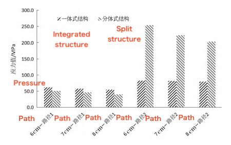
Figure 7. Stress Trends of Bonnet Flanges with Different Thicknesses
The graph illustrates the decreasing stress levels in both one-piece and split bonnet flanges as flange thickness increases, measured across critical S1 (medium pressure) and S2 (bolt preload) regions.
Finite element strength analysis of both one-piece (integrated) and split bonnet structures reveals that the critical stress concentration in both designs occurs in the region subjected solely to bolt preload. In this region, the one-piece bonnet experiences significantly lower stress compared to the split design, indicating superior performance under bolt preload conditions. Increasing flange thickness effectively improves bonnet strength in both designs; however, the one-piece bonnet requires a thicker flange to reach the same strength level as the split bonnet. Therefore, in practical valve engineering applications, choosing the right bonnet structure and ensuring sufficient flange thickness are crucial for optimizing the mechanical integrity, safety, and sealing performance of control valves.
Previous: Root Cause Analysis of Cracking in Welded Flange Globe Valve Bodies
Next: Water Pressure Management Valves: Performance and Use
