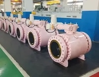
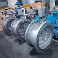
Y-Type Three-Way Ball Valve with Mechanical Interlock
To address the operational requirements for media connection and isolation in petrochemical pipelines, a three-pipe intersection layout is often adopted by design institutes due to limitations in space, flow direction, and equipment arrangement. To improve space efficiency and reduce costs, a three-way ball valve is commonly installed at pipeline intersections. A mechanical interlocking device ensures that each valve operates in a preset logical sequence through coordinated control. A Y-type three-way ball valve with a mechanical interlocking mechanism is presented in this paper. Key features include structural optimization, WC and STL20-coated sealing surfaces, a durable interlock system, and integrated signal and indicator components—collectively ensuring reliable control in complex pipeline networks.
Although technical management in the petroleum, chemical, and natural gas sectors has improved, operational errors continue to lead to safety incidents. Given the strict logical relationships between pipeline connections, any valve misoperation can result in accidents. By equipping the valve group with a rigorous mechanical interlocking system, media flow can be connected or interrupted strictly in accordance with process requirements. The selection of on-site actuators must take into account the working conditions: pneumatic actuators are bulky and rely on air supply, while electric actuators, although easy to control, pose greater risks in flammable and explosive environments. Moreover, electronic components have a limited service life, involve high maintenance costs, and cannot achieve mechanical interlocking. Therefore, in scenarios where automation is not required, pipe diameters are moderate, and control budgets are constrained, manually operated or gear-reduced valves equipped with mechanical interlocking devices represent the optimal solution. This device is purely mechanical, containing no electronic components, and offers advantages such as low cost, high stability, and enhanced safety. Its clearly defined lock numbers and key codes allow for precise control of individual valve operations while enabling logical joint control of multiple valves. This significantly reduces the risk of human error and enhances the overall safety and reliability of system operations.
At pipeline intersections, the Y-type three-way ball valve connects three pipelines at a single junction, allowing the flow direction of the fluid to be controlled by rotating the internal closure element. It ensures that the fluid medium switches between pipelines according to a predetermined sequence. Compared to conventional T-type and L-type three-way ball valves, the Y-type design offers distinct and irreplaceable advantages. Its most notable feature is its low flow resistance: the fluid passes through the valve at a 120° transition angle, providing a smoother and less obstructed flow path. This is a substantial improvement over the sharp 90° angles in T-type and L-type valves, significantly reducing pressure loss and enhancing flow efficiency.
The main components of conventional Y-type three-way ball valves—typically the valve body and bonnet—are generally produced through casting. However, this process is prone to internal defects such as sand holes, porosity, inclusions, and shrinkage cavities. Detecting these defects through X-ray inspection at the incoming material stage is labor-intensive, time-consuming, and significantly increases production costs. If defects are discovered during machining or final inspection, welding repairs are often required, potentially delaying delivery schedules. To accelerate production and improve sealing performance, conventional designs typically use soft plastic seals on the valve seat surfaces. While suitable for clean media pipelines, these seals are not ideal for petrochemical applications involving particulate matter or slag. When such media flows through the valve, solid contaminants can adhere to the ball surface. During operation, these particles may abrade the soft sealing surface, causing significant damage after only a few opening and closing cycles, and eventually leading to seal failure. Most conventional Y-type three-way valves adopt a single-piston effect (SPE) unidirectional seat design. During operation, the medium can gradually enter the valve cavity. As internal pressure builds, the structural characteristics of the SPE seat may cause it to shift in the opposite direction, often resulting in internal leakage.

Figure 1 A conventional Y-type three-way ball valve structure
This paper presents a Y-type three-way ball valve equipped with a mechanical interlocking device, designed to enable coordinated control of valve groups in pipeline networks. The mechanical interlocking system effectively prevents human error and allows process control based on logical code relationships across multiple valves.
The key structural upgrades include:
An integrally forged valve body and bonnet;
Supersonic spraying of WC and STL20 coatings on the ball and seat sealing surfaces for enhanced durability;
A scraper-type design for the valve seat sealing surface to resist particle damage;
A double-piston effect (DPE) valve seat structure for improved bidirectional sealing;
Dust rings added at the valve seat inlets/outlets, upper stem, and lower shaft bearing interfaces to prevent the ingress of particles and slag;
Integrated purge and drain functions for valve cavity cleaning;
Mechanical limit indicators for valve open/close positioning;
Signal switches and transmission functions for operational status feedback.

1. Valve bonnet 2. Valve body 3. Lower fixed shaft 4. Ball 5. Safety relief valve 6. Signal switch bracket 7. Upper pressure cover 8. Upper valve stem 9. Connecting plate 10. Interlock device connection plate 11. Limit plate 12. Handle 13. Double nut 14. Connecting rod 15. Signal switch 16. Lower valve seat dust seal 17. O-ring 18. Valve seat 19. Upper valve seat dust seal 20. Cylindrical spring 21. Fire-safe ring on valve seat 22. Upper stem bearing 23. Upper stem dust seal 24. Lower shaft bearing 25. Lower shaft dust seal 26. Position indicator block 27. Indicator needle 28. Limit pin 29. Lock plate A 30. Key A 31. Lock plate B 32. Key B 33. Drain connector 34. Purge connector
Figure 2. The optimized Y-type three-way ball valve with mechanical interlocking device

Figure 3. The Y-type three-way ball valve with mechanical interlocking device
As shown in Figures 2 and 3, the mechanical interlocking device is typically installed on the manual operator or gear reducer of the Y-type three-way ball valve. It consists of two lock plates, two corresponding keys, and fixed mounting plates. Within the pipeline network, valves are connected either in series or in parallel, and each valve’s interlocking device is assigned a unique lock-and-key code. The system-authorized keys control the opening and closing of each valve, thereby managing the flow cutoff across the pipeline network in accordance with the intended logic sequence. The main components, such as the valve body and bonnet, are integrally forged, effectively eliminating common casting defects such as porosity, inclusions, and shrinkage cavities. This design minimizes the need for post-processing repairs due to material flaws and shortens production lead time. The upgraded structure is suitable for petroleum and chemical applications involving media that contain particles and slag. The ball surface is coated with a WC (tungsten carbide) layer via supersonic spraying, achieving a surface hardness of 68–72 HRC. The valve seat sealing surface is coated with STL20 using the same method, reaching a hardness of approximately 55–58 HRC. The hardness of the ball is maintained at least 5 HRC higher than that of the valve seat to prevent damage to the spherical surface caused by friction with the seat and to resist wear from hard particles in the media.
To further enhance durability, the valve seat features a scraper-type structure. During valve operation, the scraper automatically removes particles and slag from the ball surface, preventing damage to both the ball and the sealing surface. This design improves sealing performance and extends the valve’s service life. A detailed schematic of the scraper-type seat structure is shown in Figure 4.

Figure 4 Scraper-type valve seat structure
Additionally, the design features a DPE (Double Piston Effect) valve seat, which produces a sealing force at either the inlet or the middle cavity when pressurized. The principle is as follows: when pressure is applied at the valve inlet, the sealing boundary area (E1) exceeds the inner diameter area (E2) of the valve seat, creating a pressure differential that generates sealing force. This creates a pressure differential toward the inlet, resulting in an effective sealing force. Similarly, when pressure builds up in the valve’s middle cavity, the pressure area at the outer diameter (E3) of the valve seat exceeds that at the reverse sealing boundary (E4). This generates a pressure differential toward the middle cavity, producing a sealing force in that direction. To further enhance safety, a pressure relief valve is installed at the bottom of the valve body. It is preset to open at 1.33 times the valve’s nominal pressure and reseat at 1.05 times the nominal pressure. This ensures that the valve seat maintains a reliable seal in both the forward and reverse directions while preventing abnormal pressurization of the middle cavity. This design not only guarantees effective sealing performance but also significantly enhances the overall safety of the valve.

Figure 5 Double Piston Effect (DPE) of the Valve Seat
The valve seat features upper and lower dust rings at the pressure inlets. These not only allow pressure to enter the valve seat cavity to generate a piston effect but also prevent particles and slag from entering the O-ring and spring cavities. A dust ring is also installed at the bearing inlet of the lower fixed shaft, and another at the bearing inlet of the upper valve stem. These components effectively prevent particles and slag from entering the bearing cavities, which could otherwise lead to seizure of the upper valve stem or lower fixed shaft, obstructing ball rotation and significantly increasing torque.
Over prolonged use, particles from the medium tend to settle and accumulate in the valve body cavity. Excessive sediment buildup can restrict the space available for ball rotation, potentially preventing the ball from turning altogether. To ensure proper valve operation, regular maintenance is necessary. Before performing maintenance, make sure the valve cavity is fully depressurized. The cavity can then be purged using the purge connector located on the top of the valve body. After purging, a soaking agent and cleaning solution can be introduced to flush out accumulated residue. The bottom of the valve body is fitted with a drain connector for discharging the cleaning fluids and debris. During purging and cleaning, unscrew the drain connector to discharge the cleaning fluid and contaminants from the cavity. After maintenance is complete, retighten both the purge and drain connectors.
A combination of position indication components, including the indicator block, indicator needle, limit pin, and limit plate, is installed along the three flow channels of the valve. These components restrict the ball’s rotation to the designated 120° range and clearly indicate the flow direction of the Y-type three-way valve. This built-in guidance helps prevent incorrect assembly and minimizes rework during installation. The valve position switch is bracket-mounted and mechanically coupled to the stem through a linkage rod secured by double-locking nuts. The visual open/close indicator provides immediate status feedback to operators. For remote control applications, the position switch can be wired to the plant's signal loop, transmitting real-time valve status data to the pipeline control system. This enables operators to monitor and respond to valve conditions remotely, ensuring informed decision-making based on live feedback.
The pipeline network consists of storage tanks, reactors, controllers, valves, pipelines, and other equipment. Valves play a critical role in regulating and isolating the flow of media within the system. The opening and closing states of each valve in the valve group must be strictly controlled in accordance with the prescribed operating procedure. The mechanical interlock device is mounted on the valve’s manual actuator or gear reducer, with each valve assigned a predefined interlock key code. Valve operation must conform to this logic code to ensure coordinated and safe control of the entire valve group within the pipeline network. Each mechanical interlock device consists of two plate locks and their corresponding keys, designated as plate lock A with key A, and plate lock B with key B. To operate the valve, both keys must be inserted into their respective plate locks simultaneously. When the valve is in either the fully open or fully closed position and no further operation is needed, only one key remains in the plate lock:
If key A remains, the valve is in the open position.
If key B remains, the valve is in the closed position.
To operate a valve equipped with a mechanical interlock, follow these steps:
- When the valve is closed, key B should remain inserted in plate lock B.
- To open the valve, the operator must submit a written request to the pipeline network operation control room to obtain the authorization key A.
- Once both key A and key B are inserted into the interlock device, the valve can be gradually opened while monitoring the position indicator or signal switch.
- If the valve is to remain in the open position, key B should be removed and returned to the operation control room for verification and storage. Key B will then serve as the authorization key for closing the valve during the next operation.
Each valve in the pipeline valve group is assigned a unique set of interlock key codes. Each valve is assigned a unique pair of keys—A1 and B1 for valve 1, A2 and B2 for valve 2, and so on. To verify the status of any valve, the on-site operator simply refers to the key combination record maintained in the control room (e.g., A1B2A3B4B5A6). This system ensures that valve operations strictly follow the programmed logic, significantly enhancing operational reliability and reducing the risk of human error. To enhance operational safety, this design incorporates multiple protective features, including mechanical interlocks, signal feedback systems, limit mechanisms, and safety relief valves. These measures effectively safeguard against incorrect operation, misalignment, and internal cavity overpressure, thereby significantly enhancing the system’s overall safety.
With advancements in modern industrial technology, stringent safety regulations in the petroleum and chemical industries have necessitated critical upgrades to pipeline infrastructure. As key control components within pipeline networks, valves play a decisive role in maintaining system stability through their safety features and coordinated control functions. To meet the demands of high-safety applications, this paper presents a Y-type three-way ball valve equipped with a mechanical interlock device. The design incorporates several innovations that go beyond conventional structures:
- Integral forged valve body for enhanced structural integrity.
- WC/STL20 coating applied by supersonic spraying on the ball and seat sealing surfaces, providing superior wear and corrosion resistance.
- Scraper-type seal combined with a DPE dual-piston seat design to ensure reliable sealing under extreme conditions.
- Integrated purge, cleaning, and blowdown functions to improve maintenance efficiency.
The purely mechanical interlocking system eliminates reliance on electronic components, providing inherent advantages in simplicity, cost-effectiveness, and fail-safe reliability by effectively preventing human misoperation. Field performance confirms exceptional adaptability to complex operating conditions, exceeding user expectations—particularly in flammable and explosive environments where operational safety is paramount.