Design and Manufacturing of Cryogenic Helium Bellows-Sealed Globe Valves
This paper presents the design and development of cryogenic bellows-sealed helium globe valves for the helium purification system of a 600 MW high-temperature gas-cooled reactor (HTGR) demonstration project. The valves are designed to handle highly permeable helium gas at temperatures as low as −196 °C. The leakage requirements are particularly stringent, with allowable internal and external leakage rates of less than 10⁻⁵ Pa·m³/s and 10⁻⁷ Pa·m³/s, respectively.
The study addresses three key technical challenges:
- Sealing reliability: Maintaining reliable sealing performance under helium service conditions.
- Cryogenic material performance: Preventing brittle fracture at extremely low temperatures.
- Machining precision: Achieving the required machining accuracy for ultra-long, slender valve stems.
To address these challenges, the valve incorporates a conical valve-seat sealing surface and a combined bellows-and-packing stem seal. The sealing structure was optimized, suitable cryogenic materials were selected, and the machining process for the slender valve stem was refined. Cryogenic immersion tests and helium mass spectrometry leak tests confirmed that the prototype met all specified technical requirements. The design and manufacturing technology has since been applied to equipment delivered for the project, providing technical support for the localization of critical valves used in high-temperature gas-cooled reactors.
The High-Temperature Gas-Cooled Reactor (HTGR) is a fourth-generation nuclear power technology characterized by inherent safety, versatile applications, and modular design. It is often referred to as a "meltdown-proof" reactor. China has built the world's first pebble-bed modular high-temperature gas-cooled reactor nuclear power plant, known as the HTR-PM. The Huaneng Shidaowan HTGR demonstration project entered commercial operation in December 2023, achieving an equipment localization rate of 93.4%. Building on this achievement, China is continuing to develop 600 MW-class HTGR demonstration projects.
Helium, the primary coolant in HTGRs, offers excellent thermal conductivity and a low neutron absorption cross-section. However, its small molecular diameter (approximately 0.26 nm), low molecular weight, and high diffusivity make it highly prone to leakage through sealing interfaces. Conventional valve-seat sealing structures and spiral-wound gaskets cannot adequately meet the stringent leakage limits of less than 10⁻⁵ Pa·m³/s for internal leakage and 10⁻⁷ Pa·m³/s for external leakage. In addition, exposure to cryogenic temperatures as low as −196 °C presents challenges related to brittle fracture, phase instability, and mismatched thermal contraction. Consequently, the sealing performance of helium globe valves is critical to the safe operation of nuclear island systems and the prevention of radioactive releases into the environment.
This paper focuses on the development of a cryogenic bellows-sealed helium globe valve for 600 MW-class high-temperature gas-cooled reactors (HTGRs). The objective is to address the sealing challenges posed by the combined effects of extremely low temperatures (−196 °C) and helium's high permeability, thereby enabling the domestic development and manufacture of this critical equipment. Because the valve handles helium, it is subject to exceptionally stringent sealing requirements. During gas-tightness testing using nitrogen with a purity of at least 99.99% at 1.1 times the nominal pressure, no bubbles are permitted at the valve seat, while no detectable leakage is permitted at the upper seal, intermediate flange, or packing seal. In addition, helium mass spectrometer leak testing at room temperature and operating pressure must demonstrate an internal leakage rate below 10⁻⁵ Pa·m³/s and an external leakage rate below 10⁻⁷ Pa·m³/s. Meeting these requirements calls for systematic research and development, together with experimental validation, to ensure that the valve design and manufacturing processes satisfy engineering application requirements.
The valve investigated in this study is a cryogenic bellows-sealed globe valve, with its key performance parameters listed in Table 1. It has a Class 800 pressure rating, a design pressure of 8 MPa, and a design temperature range of −196 °C to 200 °C. The external leakage rate must not exceed 1 × 10⁻⁷ Pa·m³/s, both before and after operational cycling, and the specified service life is 40 years.
Table 1 Key Parameters of the Cryogenic Bellows-Sealed Helium Globe Valve
Parameter | Specification |
Nominal Size | DN 40 |
Pressure Class | Class 800 |
Design Pressure | 8 MPa |
Design Temperature | −196 °C to 200 °C |
Working Medium | Helium |
External Leakage Rate | ≤ 1 × 10⁻⁷ Pa·m³/s |
Internal Leakage Rate | ≤ 1 × 10⁻⁵ Pa·m³/s |
Service Life | 40 years |
The bellows-sealed globe valve consists of a valve body, disc, bonnet, stem, bellows assembly, and electric actuator, as shown in Figure 1. The valve body and bonnet are connected by a central flange, facilitating assembly and disassembly. The stem features a dual-sealing arrangement consisting of a bellows and packing, with the packing providing secondary sealing in the event of bellows failure. The valve disc and seat have conical sealing surfaces, which provide good self-centering capability and reliable sealing performance. The stem and disc are separate components, allowing the disc to pivot through a small angle and thereby facilitating automatic alignment with the valve seat.
The valve body and bonnet feature an extended-neck design. The extended section is made of seamless steel pipe of the same material as the valve body and is butt-welded to the bonnet and stuffing box. Post-weld heat treatment is then performed to relieve residual stresses. The extended neck has a length-to-diameter ratio of 9:1. This design allows heat exchange with the surrounding environment, resulting in a gradual temperature increase from the bottom to the top of the extended section. As a result, the temperature at the base of the stuffing box remains above 0 °C, helping maintain effective packing sealing performance.
For service under extremely low-temperature conditions, the primary pressure-retaining components, including the valve body, bonnet, and disc, are made of austenitic stainless steel (NB/T 47010 S31608 (III)). Owing to its face-centered cubic (FCC) crystal structure, this material retains excellent toughness at cryogenic temperatures and does not exhibit a ductile-to-brittle transition temperature. The bellows are made of Type 316Ti stainless steel, while the valve stem is manufactured from high-strength stainless steel (SA-182M FXM-19). The sealing surfaces are hardfaced with Stellite to improve wear resistance and sealing performance.
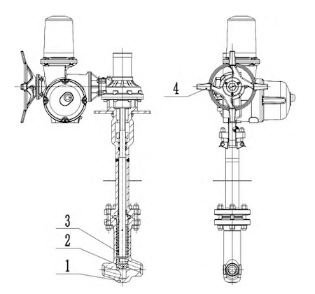
Figure 1. Schematic of a Cryogenic Bellows-Sealed Helium Globe Valve
- Valve body
- Valve disc
- Bellows assembly
- Electric actuator
Owing to its small molecular diameter (approximately 0.26 nm), low viscosity, and high diffusivity, helium is widely used as a tracer gas for leak detection. Cryogenic helium globe valves are subject to stringent leakage limits, with an allowable external leakage rate of no more than 1 × 10⁻⁷ Pa·m³/s and an internal leakage rate of no more than 1 × 10⁻⁵ Pa·m³/s. These limits are two to three orders of magnitude more stringent than those typically applied to conventional industrial valves. Traditional flat sealing structures are inadequate for helium service because helium molecules can penetrate extremely small gaps. Even apparently smooth sealing surfaces contain microscopic irregularities that may form leakage paths. Furthermore, under actual HTGR operating conditions, valves are subjected to combined loads, including thermal cycling, pressure fluctuations, and vibration, which further increase the risk of seal failure. Therefore, targeted optimization is required for both the valve-seat seal, which prevents internal leakage, and the stem seal and bonnet flange, which prevent external leakage.
(1) Optimization of the Internal Sealing Structure
To meet the internal leakage limit of less than 10⁻⁵ Pa·m³/s, the valve seat is designed with a conical sealing surface, as shown in Figure 2. The disc sealing surface is hardfaced with Stellite 6 (STL6), while the valve seat sealing surface is hardfaced with Stellite 12 (STL12). The half-cone angle of the sealing surface, α, is 30°. This conical sealing design offers three main advantages. First, during valve closure, the disc wipes the sealing surfaces, helping remove graphite particles from the medium. Second, the conical geometry produces a wedging effect, generating higher contact pressure under the same axial force. Third, it provides effective guidance for the disc, reducing the risk of misalignment.
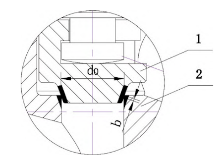
Figure 2. Schematic of the Conical Sealing Surface Structure
- Valve disc
- Valve seat
The axial force Q required to achieve helium-tight sealing in the valve is calculated using the following formula:

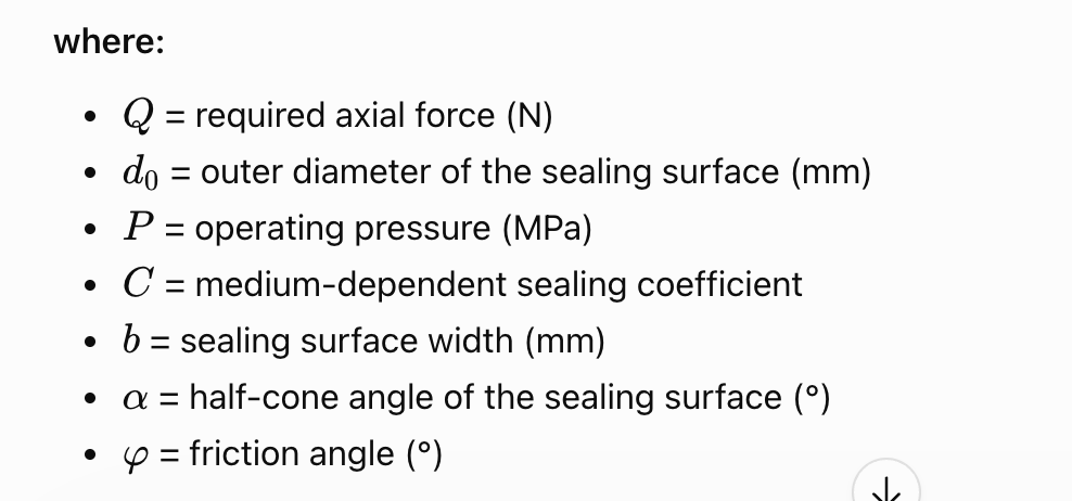
The sealing surface width and operating torque are determined to ensure that the contact pressure remains within the specified range, between the minimum required value and the maximum allowable value. Surface roughness is another critical factor affecting helium-tight sealing performance. Research on helium isolation valves for high-temperature gas-cooled reactors indicates that the optimal sealing performance is achieved when the surface roughness (Ra) of the sealing pair is 0.63 µm. At this roughness, microscopic surface asperities interlock to form a tortuous leakage path, creating a "labyrinth effect" that progressively dissipates the pressure of helium passing through the sealing interface. If the surface roughness is too high (Ra > 0.63 µm), larger leakage channels may form, potentially allowing helium to pass through more readily. Conversely, if the roughness is too low (Ra < 0.63 µm), the interlocking effect between surface asperities is weakened, reducing the effectiveness of the labyrinth effect in restricting helium leakage. Therefore, the surface roughness of the sealing surfaces in this design is controlled at Ra = 0.63 µm.
(2) Optimization of the External Sealing Structure
To meet the stringent external leakage limit of less than 10⁻⁷ Pa·m³/s, a dual-sealing design is adopted. At the valve stem, the bellows serves as the primary seal, with the stuffing box providing backup sealing. At the bonnet flange (mid-flange), a combination of a metal C-ring and a spiral-wound gasket provides dual sealing. As shown in Figure 3, the bellows assembly consists of the valve stem, bellows, and bellows guide sleeve, which are joined by welding. A multilayer 316Ti stainless steel bellows is selected for its excellent corrosion resistance and fatigue performance, with a design life of more than 5,000 operating cycles. The lower end of the bellows is welded to the valve stem, while its upper end is welded to the guide sleeve, forming a closed pressure boundary. During valve operation, the bellows expands and contracts to accommodate stem movement, eliminating the leakage path associated with a conventional dynamic stem seal.
To provide backup sealing in the event of bellows failure, a stuffing box is installed above the bellows. Flexible graphite is used as the packing material, with a spacer ring installed between the packing sections to ensure uniform load distribution. A set of disc springs is fitted to the packing gland to provide a live-loading function, automatically compensating for packing relaxation and helping maintain sealing pressure.
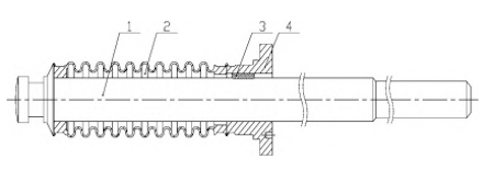
- Valve stem
- Bellows
- Key
- Bellows guide sleeve
Figure 3. Schematic of the Bellows Assembly
The mid-flange sealing arrangement combines a metal C-ring with a spiral-wound gasket, as illustrated in Figure 4. The metal C-ring consists of an internal helical spring, an intermediate alloy layer, and an outer PTFE coating. The helical spring, made of Inconel 718, provides excellent resilience to accommodate variations in operating conditions, while the Inconel 718 alloy layer provides structural support and transmits the contact load. The outer PTFE coating, with a thickness of 50–70 µm, exhibits an elongation of approximately 5% at −196 °C. It retains its flexibility and mechanical strength without becoming brittle or cracking at cryogenic temperatures, thereby ensuring long-term sealing reliability. The spiral-wound gasket consists of an inner metal ring and an outer flexible graphite winding. Under high compressive loads, the inner metal ring prevents excessive compression of the gasket, while the graphite winding provides effective sealing.
The dimensions of the groove for the metal C-ring are critical to sealing performance. The groove depth, H, determines the compression of the C-ring. In this design, H is 3.24 ± 0.05 mm to ensure an appropriate compression range. The groove width, L, is 7 mm, and the groove surface roughness must not exceed 0.8 µm. These requirements facilitate C-ring installation and provide sufficient clearance for the machining and grinding tools. The groove outer diameter, φ, is 66 mm, compared with an outer diameter of 65.45 mm for the C-ring, providing positioning support. Calculations indicate that the metal C-ring can withstand a load of 98,663 N, well above the 56,872 N required for helium leak testing, thereby confirming its adequate load-bearing capacity and sealing reliability.
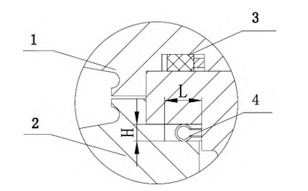
- Valve bonnet
- Valve body
- Spiral-wound gasket
- Metal C-ring
Figure 4. Schematic of the Mid-Flange Sealing Arrangement
For valves designed to operate at temperatures as low as −196 °C, the materials used for the main components face three primary challenges. First, low-temperature brittle fracture may occur without noticeable prior plastic deformation, posing a significant safety risk. Second, martensitic transformation induced by low temperatures may further increase the risk of embrittlement. Third, thermal contraction and differences in the thermal expansion of component materials can generate additional stresses, potentially leading to sealing failure, stress concentration, and subsequent cracking. To address these challenges, the following measures are implemented:
(1) Austenitic stainless steel F316 is selected for the main components. Owing to its face-centered cubic (FCC) crystal structure, this material exhibits excellent low-temperature toughness and ductility, with no pronounced ductile-to-brittle transition at temperatures down to −196 °C. It therefore provides effective resistance to brittle fracture and retains good impact toughness even at liquid nitrogen temperatures. The valve stem is made of nitrogen-strengthened, high-performance stainless steel (FXM-19), which combines high strength with excellent low-temperature toughness.
(2) Flexible graphite is used for the sealing components. The coefficient of thermal expansion of graphite-based nonmetallic sealing materials is closer to that of austenitic stainless steel than that of many other nonmetallic materials, helping maintain reliable sealing over a wide temperature range. Tests have confirmed that flexible graphite retains good elasticity and sealing performance at −196 °C. In addition, the levels of impurities such as chlorides and sulfur compounds are strictly controlled, with chloride content limited to 50 ppm and total sulfur content to 100 ppm, to reduce the risk of stress corrosion cracking in the austenitic stainless steel.
(3) The structural design is optimized to minimize stress concentrations. Large-radius fillets are incorporated at transitions between sections of all pressure-retaining components to avoid sharp notches and abrupt changes in cross-sectional area. The design is evaluated in accordance with ASME BPVC Section III, NB-3520, to ensure that critical sections, such as the valve body neck, remain within the specified stress limits under the combined effects of low-temperature thermal stresses, internal pressure, and seismic loads. When determining the flange bolt preload, the effects of thermal contraction at low temperatures are also taken into account. The thermal deformation is calculated using the following equation:
ΔL = (L₁ − L₂) · α · (t₁ − t₂)
This calculation helps ensure reliable flange sealing under both high- and low-temperature operating conditions.
(4) Cryogenic Treatment of Pressure-Retaining Components
To further improve the performance stability of valves under extremely low-temperature conditions, a cryogenic treatment process is investigated. The process involves cooling the material to −196 °C to promote the transformation of retained austenite into martensite. For critical valve components designed to operate at temperatures below −101 °C, cryogenic treatment must be performed before finish machining. The components are immersed in liquid nitrogen, and the holding time is measured from the point at which boiling at the liquid nitrogen surface ceases. The components are held at −196 °C for 2 hours when the maximum workpiece thickness is 50 mm or less, and for 3 hours when it exceeds 50 mm.
The effectiveness of cryogenic treatment depends on precise control of the cooling rate, holding time, and warming rate. Research indicates that austenitic steels intended for service at temperatures below −100 °C should undergo at least two cryogenic treatment cycles to improve their material properties, thereby enhancing valve service life and operational reliability under extremely low-temperature conditions. Cryogenic treatment can also help stabilize the material's microstructure and relieve residual stresses introduced during machining, thereby improving dimensional stability.
The stem of a cryogenic bellows-sealed valve has a much higher length-to-diameter ratio than that of a conventional valve, making it particularly challenging to machine. With an overall length of more than 740 mm and a diameter of only 24 mm, the stem has a length-to-diameter ratio of approximately 30:1, classifying it as a typical slender shaft. During machining, such components are susceptible to elastic deformation, bending, vibration, and tool deflection. These problems can result in poor dimensional accuracy, unsatisfactory surface finish, and deviations in coaxiality, potentially leading to component rejection.
To address the challenges of machining these slender valve stems, a specialized fixture was designed and the machining process was optimized. As shown in Figure 5, the fixture adopts a "one-chuck, one-center" configuration, with the workpiece clamped at one end and supported by a center at the other. A three-jaw chuck secures the workpiece at the spindle end, while a revolving center supports it at the tailstock end. The alignment between the revolving center and the spindle axis is carefully calibrated to ensure that the valve stem's axis of rotation coincides with the spindle axis, thereby minimizing bending deformation.
An adjustable steady rest is positioned at the midpoint of the valve stem to provide auxiliary support and compensate for its limited rigidity. The steady rest contact points are made of nylon or copper alloy to prevent damage to the machined surfaces. During machining, the support force is adjusted in real time to accommodate variations in the valve stem diameter, providing effective support without excessively constraining the workpiece.
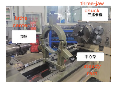
Figure 5. Valve stem machining fixture
A "shallow depth of cut and high feed rate" strategy is adopted to reduce radial cutting forces. The tool rake angle is increased to 15°–20° to reduce cutting deformation and cutting forces, while a small tool nose radius of R0.2–0.4 mm is selected to minimize friction. The machining process is divided into several stages. Stress-relief annealing is performed after rough machining to relieve residual stresses, followed by natural aging after semi-finish machining and subsequent finish machining. The machining allowance at each stage is strictly controlled to minimize deformation caused by stress release. With these process optimizations, a prototype valve stem was successfully manufactured, as shown in Figure 6. Inspection results confirm that the roundness, cylindricity, and straightness meet the design specifications, and the surface roughness is Ra 6.3 µm. These results provide a sound basis for ensuring the overall performance of the valve.
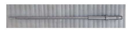
Figure 6. Valve stem prototype
To verify the valve's sealing performance and operational reliability at an extremely low temperature of −196 °C, a series of systematic cryogenic tests was conducted. The test setup is shown in Figure 7.
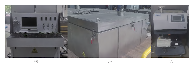
(a) Cryogenic measurement and control system (b) Cryogenic chamber system (c) Helium mass spectrometer leak detector
Figure 7. Cryogenic test apparatus
The test procedure consists of three stages: ambient-temperature performance testing, cryogenic immersion testing, and cryogenic endurance (life) testing, as shown in Figure 8. First, routine performance tests are conducted on the valve at ambient temperature to establish baseline performance data. These tests include a shell hydrostatic test at 1.5 times the design pressure, a seat tightness test using nitrogen at 1.1 times the design pressure, and tests of the backseat and packing seals.
Next, the valve undergoes a cryogenic immersion test. The entire valve is immersed in a liquid nitrogen tank, while multiple temperature sensors monitor key components, including the valve body, bonnet, and stem. Once the temperatures at all monitored points reach and stabilize at −196 °C, this temperature is maintained throughout the test. Helium gas is then introduced, and the test pressure is raised to 6.9 MPa. The internal leakage rate across the valve seat is measured using a helium mass spectrometer leak detector in sniffing mode. The pressure is subsequently increased to 14.6 MPa to measure external leakage at the valve stem and bonnet flange using the same detector and method. The tests are conducted in accordance with GB/T 24925, Technical Specifications for Cryogenic Valves.
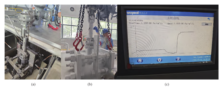
(a) Preparation for cryogenic testing (b) Cryogenic testing in progress (c) Helium mass spectrometer leak test results
Figure 8. Cryogenic test procedure and results
Finally, a cryogenic operational life test is conducted. With the temperature maintained at −196 °C, the valve undergoes 202 opening and closing cycles. Helium leak tests are repeated at specified intervals to monitor changes in the leakage rate. Upon completion of the test, the data are compiled and analyzed. The initial cryogenic helium leak test results are compared with those obtained after 202 cycles to evaluate the stability of the valve's sealing performance under cryogenic conditions.
The test results show that, in the initial state at ambient temperature, the prototype valve had an internal helium leakage rate of 2.9 × 10⁻⁸ Pa·m³/s and an external leakage rate of 2.49 × 10⁻⁹ Pa·m³/s. Both values were well below the limits specified in the technical documentation. After cryogenic immersion, the initial leak test showed slight increases in both internal and external leakage rates, although both remained within the specified limits. As the number of operating cycles at cryogenic temperatures increased, the leakage rates exhibited a gradual upward trend. After 202 cycles, the internal leakage rate reached 1.55 × 10⁻⁶ Pa·m³/s, while the external leakage rate reached 8.2 × 10⁻⁹ Pa·m³/s. Both values remained within the limits specified in the technical requirements. The test results are presented in Table 2.
Table 2. Comparison of Test Results at Ambient and Cryogenic Temperatures
Test Item | Ambient-Temperature Test | Initial Cryogenic Test | Cryogenic Test After 202 Cycles |
Internal Leakage (Pa·m³/s) | 2.90 × 10⁻⁸ | 1.66 × 10⁻⁷ | 1.55 × 10⁻⁶ |
External Leakage (Pa·m³/s) | 2.49 × 10⁻⁹ | 5.55 × 10⁻⁹ | 8.20 × 10⁻⁹ |
Throughout the tests, the valve opened and closed normally and operated smoothly, without jamming or abnormal noise. Post-test disassembly and inspection showed that the sealing surfaces remained in good condition, with no significant wear. The bellows exhibited no residual deformation, and the packing remained undamaged. These results demonstrate that the valve's structural design, material selection, and manufacturing processes provide reliable performance, enabling it to meet the stringent helium leak-rate requirements at −196 °C.
In this study, a cryogenic bellows-sealed helium globe valve designed to operate at −196 °C was successfully developed for 600 MW-class high-temperature gas-cooled reactors (HTGRs). The key technical challenges addressed included achieving helium-tight sealing, ensuring reliable performance under extreme cryogenic conditions, and precision machining of a slender valve stem with a length-to-diameter ratio of 30:1. Through structural optimization, appropriate material selection, and manufacturing process improvements, the valve achieved reliable low-leakage performance in helium service. Cryogenic immersion tests and helium mass spectrometer leak tests confirmed that the valve met the sealing and operational requirements of cryogenic helium systems. The research established a comprehensive set of design and manufacturing solutions that have been successfully applied in engineering practice, providing a basis for the domestic development and manufacture of critical HTGR valves and delivering significant engineering and economic benefits.

Latest News
Design and Manufacturing of Cryogenic Helium Bellows-Sealed Globe Valves
Analysis and Remedial Measures for Operating Seal Leakage in Ball Valves of High-Head Pumped-Storage Units