3 Way Ball Valves
The series O-type Three-way ball valve has characteristics of large circulation capacity, compact structure, good sealing performance, long life, etc., economical and practical, and easy to maintain. It is widely used in petroleum, chemical, natural gas, electric power, metallurgy, food, pharmaceutical and other occasions with strict requirements. It can also be applied to water, steam, oil, liquefied gas, natural gas, coal gas and other media.
In addition, special hardening treatments can be selected according to customer needs, suitable for -196 - 400 ℃, providing safer and more extensive applications.
Three-Way Flange Ball Valve

Three-way thread ball valve

Features
1. The valve body adopts precision casting or forging, with a compact structure and beautiful appearance. The spool and stem of the O-type three-way ball valve make a rotating movement. When the spool is turned, the spool and valve seats are always in close contact with each other, which has a strong shearing ability;
2. The valve seat can be designed to be preloaded by a cylindrical spring or butterfly spring, with automatic compensation, self-sealing and automatic pressure relief in the valve cavity, suitable for high temperatures and high-pressure occasions;
3. The rotating design of the valve ball can ensure the smooth operation of the valve ball and reduce the operating torque;
4. There are optional soft and hard seals, and the sealing surface can be hardened, suitable for a variety of working conditions;
5. The automatic pressure relief design of the valve middle cavity. When the medium temperature of the valve body cavity rises and causes abnormal pressure increase, it does not need to pass the safety valve. Still, it can automatically relieve pressure only by the function of the valve seat, which improves the safety of the valve when conveying liquid medium.
6. Emergency fat injection rescue, in some special occasions, due to foreign objects in the medium or fire caused by the accidental failure of the valve seat seal, the grease injection valve provides a quick connection with the grease injection gun, which is convenient and quick to inject the sealing grease into the valve seat sealing part To mitigate the leak;
7. Ball valve Antistatic design, Anti-flying design of valve stem;
8. The elongated stem design is suitable for low-temperature applications;
9. Three-way ball valve Any port can be used as an inlet without leakage, It can be made into L-shaped or T-shaped channels according to the working conditions, which makes installation more convenient;
10. Inspection and maintenance can be performed without removing the entire valve body after the system is relieved of pressure;
11. Three-way ball valves are divided into L-type and T-type. L-type is suitable for medium flow switching, which can connect two channels perpendicular to each other. T-type is suitable for medium splitting, confluence or flow direction switching;
12. The two-seat sealed three-way ball valve has a compact structure, beautiful appearance, and good sealing performance. It can switch the flow direction of the pipeline medium, and can also connect or close the two perpendicular channels;
13. The four-seat sealed three-way ball valve has a beautiful shape and reasonable structure, which can not only realize the switching of the medium flow direction, but also make the three channels communicate with each other, and flexibly control the merge or split flow of the medium in the pipeline;
14. Any port of the four-way ball valve can be used as an inlet without leakage, and can be made into various types of channels according to the working conditions, making the installation more convenient;
15. The four-seater sealed four-way ball valve has a beautiful shape and reasonable structure, which can not only realize the switching of the medium flow direction, but also make the four channels communicate with each other, and flexibly control the merge or split flow of the medium in the pipeline.
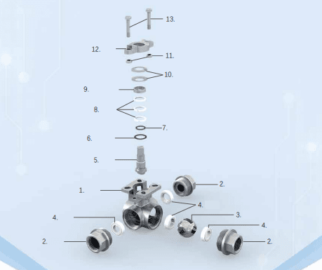
Main parts materials
| NO. | Part Name | Material |
| 1 | Body | ASTM A216 WCB, ASTM A351 CF8, ASTM A351 CF8M, CF3M |
| 2 | Bonnet | ASTM A216 WCB, ASTM A351 CF8, ASTM A351 CF8M, ASTM A351 CF3M |
| 3 | Ball body | SS 304, SS 316, SS 316L, SS 316L + STL |
| 4 | Seat | PTFE, PPL, Metal seal, etc. |
| 5 | Cover board | ASTM A216 WCB, ASTM A351 CF8, ASTM A351 CF8M, ASTM A351 CF3M |
| 6 | Middle head gasket | PTFE, PPL, Metal gasket |
| 7 | Stem | SS 304, SS 316, SS 316L, 17-4PH, S20910 |
| 8 | Inverted seal | PTFE, PPL, Stainless steel wound graphite |
| 9 | O-ring | VITON |
| 10 | Filler | PTFE, PPL, Flexible graphite |
| 11 | Filling clamping ring | SS 304 |
| 12 | Butterfly spring | SS 304 |
| 13 | NUT | 2H, SS 304 |
| 14 | Gland of valve | ASTM A351 CF8 |
| 15 | Screw | ASTM B7, SS 304 |
| 16 | Screw | ASTM B7, SS 304 |

Schematic diagram of three-way flow


Product Specifications
| Nominal pressure | PN1.6-42MPa, ANSI 150 LB-2500 LB |
| Nominal diameter(mm) | DN15-DN400 |
| Connection Type | Flange, Thread, Butt welding, Socket welding |
| Body material | LCB, WCB, CF8, CF8M, CF3, CF3M |
| Valve seat form | Soft seat, metal seat (hardened sealing surface) |
| Proper temperature | Soft seat: -20 - +200℃, Metal seat: -196 - +400℃ |
| Leakage level | ANSI VI |
| Design standards | GB/T 12237, ASME B16.34 |
| Structure length | GB/T 12221, ASME B16.10 |
| Testing standards | GB/T 13927, API 598 |
| Operation method | Manual, pneumatic, electric, etc. |
| Optional | Anti-static design, fire protection design, oil-free treatment, Copper Prohibition, Spherical special treatment, Customers request painting |
Product structure design features
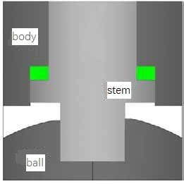
1. Valve stem anti-blowing structure design (see picture 1)
In valve stem anti-blowing structure design, the lower end is larger and the upper end is smaller. The positioning of the upper-end cover and screws, even in the valve cavity is abnormal. In this case, it can also ensure that the valve stem will not be blown out by the medium.
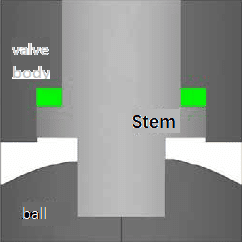
picture 1
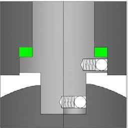
2. Anti-static design (See picture 2)
The fixed ball valve adopts an anti-static design to make the ball, stem and valve. The body forms an electrostatic channel so that the ball and the seat are switched. During the process, static electricity generated by friction is led to the ground through the valve body, Preventing the risk of fire or explosion caused by static sparks.
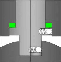
picture 2
KV rated
| SIZE | DN15 | DN20 | DN25 | DN32 | DN40 | DN50 | DN65 | DN80 | DN100 | DN125 | DN150 | DN200 | DN250 | DN300 |
| Kv | 26 | 65 | 91 | 150 | 265 | 480 | 750 | 1260 | 2300 | 3800 | 5400 | 9900 | 15000 | 25000 |
Soft seal torque table (N.m)
| SIZE | DN15 | DN20 | DN25 | DN32 | DN40 | DN50 | DN65 | DN80 | DN100 | DN125 | DN150 | DN200 | DN250 | DN300 |
| PN16 | 8 | 12 | 18 | 29 | 35 | 65 | 89 | 120 | 220 | 500 | 800 | 1400 | 1950 | 2620 |
| PN25 | 10 | 14 | 22 | 40 | 50 | 80 | 120 | 160 | 280 | 650 | 1000 | 1700 | 2400 | 3740 |
| PN40 | 14 | 20 | 48 | 60 | 70 | 100 | 200 | 300 | 500 | 900 | 1400 | 1992 | 3380 | 5600 |
| PN63 | 30 | 60 | 100 | 130 | 160 | 200 | 400 | 600 | 800 | 1200 | 1780 | 3000 | 5120 | 8580 |
| PN100 | 38 | 70 | 136 | 200 | 260 | 380 | 760 | 920 | 1540 | 1310 | 3780 | 6560 | 10500 | 14400 |
| PN160 | 48 | 88 | 170 | 250 | 306 | 476 | 900 | 1150 | 1926 | 2096 | 4639 | 8232 | 11820 | 20274 |
| CL150 | 9 | 14 | 26 | 36 | 48 | 75 | 100 | 150 | 270 | 600 | 940 | 1560 | 2210 | 3310 |
| CL300 | 17 | 25 | 55 | 90 | 110 | 140 | 280 | 350 | 620 | 1050 | 1600 | 2400 | 3472 | 4776 |
| CL600 | 38 | 70 | 136 | 200 | 260 | 380 | 720 | 920 | 1540 | 1310 | 3780 | 6560 | 10500 | 14400 |
| CL900 | 48 | 88 | 170 | 250 | 306 | 476 | 900 | 1150 | 1926 | 2096 | 4639 | 8232 | 11820 | 20274 |
| CL1500 | 64 | 110 | 230 | 285 | 342 | 592 | 1126 | 1436 | 2408 | 3810 | 7630 | 14430 | 21980 | 32206 |
| CL2500 | 98 | 165 | 345 | 430 | 520 | 1178 | 1472 | 3154 | 3930 | 4912 | 11002 | 23572 | 26444 | 40150 |
Hard seal torque table (N.m)
| SIZE | DN15 | DN20 | DN25 | DN32 | DN40 | DN50 | DN65 | DN80 | DN100 | DN125 | DN150 | DN200 | DN250 | DN300 |
| PN16-L | 18 | 22 | 31 | 42 | 62 | 88 | 126 | 192 | 308 | 650 | 1000 | 1600 | 2300 | 3000 |
| PN16-T | 34 | 42 | 59 | 80 | 118 | 167 | 239 | 365 | 585 | 1087 | 1630 | 2508 | 3302 | 5329 |
| PN25-L | 20 | 25 | 40 | 75 | 83 | 115 | 176 | 264 | 396 | 803 | 1320 | 2035 | 2453 | 4015 |
| PN25-T | 38 | 47 | 76 | 142 | 158 | 218 | 334 | 502 | 752 | 1526 | 2508 | 3866 | 4660 | 7628 |
| PN40-L | 22 | 33 | 59 | 112 | 132 | 165 | 264 | 451 | 676 | 1265 | 2156 | 2750 | 3619 | 6006 |
| PN40-T | 42 | 63 | 112 | 213 | 251 | 313 | 502 | 857 | 1284 | 2403 | 4096 | 5225 | 6876 | 11411 |
| PN63-L | 27 | 46 | 77 | 165 | 211 | 286 | 429 | 726 | 1023 | 2090 | 3245 | 4620 | 6116 | 9427 |
| PN63-T | 51 | 87 | 146 | 313 | 400 | 543 | 815 | 1379 | 1944 | 3971 | 6165 | 8778 | 11620 | 17900 |
| PN100-L | 33 | 60 | 115 | 213 | 330 | 286 | 517 | 946 | 1452 | 2178 | 3157 | 5874 | 10186 | 14982 |
| PN100-T | 63 | 114 | 218 | 405 | 627 | 543 | 982 | 1797 | 2759 | 4138 | 5998 | 11160 | 19353 | 28466 |
| PN160-L | 42 | 93 | 170 | 297 | 429 | 429 | 781 | 1419 | 2145 | 3432 | 4928 | 8635 | 17050 | 24700 |
| PN160-T | 80 | 178 | 323 | 564 | 815 | 815 | 1484 | 2696 | 4075 | 6521 | 9363 | 16406 | 32395 | 46900 |
| CL150-L | 19 | 23 | 37 | 62 | 68 | 103 | 143 | 225 | 341 | 671 | 1078 | 1595 | 2035 | 3685 |
| CL150-T | 36 | 44 | 70 | 118 | 129 | 196 | 272 | 427 | 648 | 1275 | 2048 | 3030 | 3866 | 6999 |
| CL300-L | 24 | 35 | 71 | 129 | 154 | 235 | 324 | 605 | 825 | 1628 | 2651 | 3971 | 4917 | 7645 |
| CL300-T | 46 | 66 | 125 | 245 | 293 | 446 | 616 | 1150 | 1567 | 3093 | 5037 | 7545 | 9342 | 14525 |
| CL600-L | 33 | 60 | 115 | 213 | 330 | 286 | 517 | 946 | 1452 | 2178 | 3157 | 5874 | 10186 | 14982 |
| CL600-T | 63 | 114 | 218 | 405 | 627 | 543 | 982 | 1797 | 2759 | 4138 | 5998 | 11160 | 19353 | 28466 |
| CL900-L | 42 | 93 | 170 | 297 | 429 | 429 | 781 | 1419 | 2145 | 3432 | 4928 | 8635 | 17050 | 24700 |
| CL900-T | 80 | 178 | 323 | 564 | 815 | 815 | 1484 | 2696 | 4075 | 6521 | 9363 | 16406 | 32395 | 46900 |
Note: The black part is the torque table of the floating three-way four-way ball valve, and the red part is the torque table of the fixed three-way four-way ball valve.
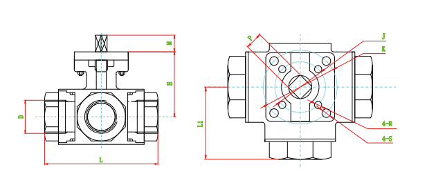
Three-Way Flange Ball Valve
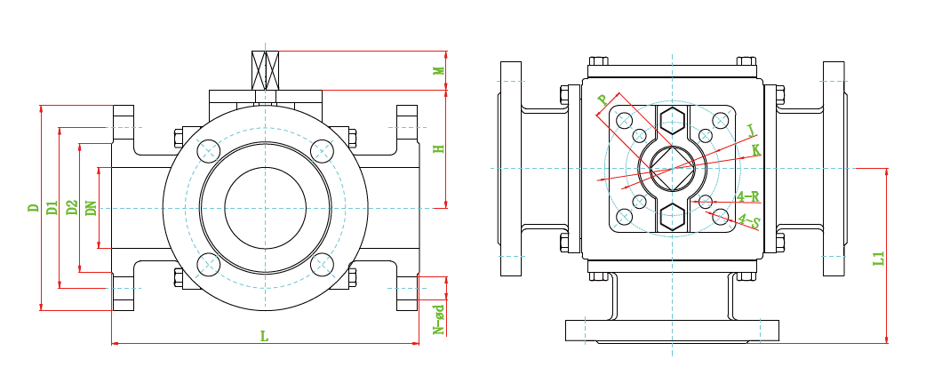
GB PN16 Main dimensions table (Unit: mm)
|
SIZE |
L |
L1 |
D2 |
D1 |
D |
N-ø d |
M |
H |
J |
K |
P |
R |
S |
|
DN15 |
150 |
75 |
45 |
65 |
95 |
4-ø 14 |
13 |
58 |
42 |
50 |
11 |
6 |
7 |
|
DN20 |
160 |
80 |
58 |
75 |
105 |
4-ø 14 |
16 |
61 |
50 |
70 |
14 |
7 |
9 |
|
DN25 |
180 |
90 |
68 |
85 |
115 |
4-ø 14 |
16 |
72 |
50 |
70 |
14 |
7 |
9 |
|
DN32 |
200 |
100 |
78 |
100 |
140 |
4-ø 18 |
16 |
81 |
50 |
70 |
14 |
7 |
9 |
|
DN40 |
220 |
110 |
88 |
110 |
150 |
4-ø 18 |
19 |
103 |
70 |
102 |
17 |
9 |
11 |
|
DN50 |
240 |
120 |
102 |
125 |
165 |
4-ø 18 |
19 |
113 |
70 |
102 |
17 |
9 |
11 |
|
DN65 |
260 |
130 |
122 |
145 |
185 |
8-ø 18 |
19 |
120 |
70 |
102 |
17 |
9 |
11 |
|
DN80 |
280 |
140 |
138 |
160 |
200 |
8-ø 18 |
24 |
162 |
125 |
140 |
22 |
14 |
18 |
|
DN100 |
320 |
160 |
158 |
180 |
220 |
8-ø 18 |
24 |
184 |
125 |
140 |
22 |
14 |
18 |
|
DN125 |
380 |
190 |
188 |
210 |
250 |
8-ø 18 |
29 |
215 |
140 |
165 |
27 |
18 |
22 |
|
DN150 |
440 |
220 |
212 |
240 |
285 |
8-ø 22 |
29 |
250 |
140 |
165 |
27 |
18 |
22 |
|
DN200 |
550 |
275 |
268 |
295 |
340 |
12-ø 22 |
38 |
334 |
|
165 |
36 |
|
22 |
|
DN250 |
670 |
335 |
320 |
355 |
405 |
12-ø 26 |
|
380 |
|
165 |
|
|
|
|
DN300 |
850 |
425 |
378 |
410 |
460 |
12-ø 26 |
|
405 |
|
165 |
|
|
|
GB PN25-PN40 Main dimensions table (Unit: mm)
|
SIZE |
L |
L1 |
D2 |
D1 |
D |
N-ø d |
M |
H |
J |
K |
P |
R |
S |
|
|
DN15 |
150 |
75 |
45 |
65 |
95 |
4-ø 14 |
13 |
58 |
42 |
50 |
11 |
6 |
7 |
|
|
DN20 |
160 |
80 |
58 |
75 |
105 |
4-ø 14 |
16 |
61 |
50 |
70 |
14 |
7 |
9 |
|
|
DN25 |
180 |
90 |
68 |
85 |
115 |
4-ø 14 |
16 |
72 |
50 |
70 |
14 |
7 |
9 |
|
|
DN32 |
200 |
100 |
78 |
100 |
140 |
4-ø 18 |
16 |
81 |
50 |
70 |
14 |
7 |
9 |
|
|
DN40 |
220 |
110 |
88 |
110 |
150 |
4-ø 18 |
19 |
103 |
70 |
102 |
17 |
9 |
11 |
|
|
DN50 |
240 |
120 |
102 |
125 |
165 |
4-ø 18 |
19 |
113 |
70 |
102 |
17 |
9 |
11 |
|
|
DN65 |
290 |
145 |
122 |
145 |
185 |
8-ø 18 |
19 |
120 |
70 |
102 |
17 |
9 |
11 |
|
|
DN80 |
310 |
155 |
138 |
160 |
200 |
8-ø 18 |
24 |
177 |
125 |
140 |
22 |
14 |
18 |
|
|
DN100 |
350 |
175 |
162 |
190 |
235 |
8-ø 22 |
24 |
184 |
125 |
140 |
22 |
14 |
18 |
|
|
DN125 |
440 |
220 |
188 |
220 |
270 |
8-ø 26 |
29 |
215 |
140 |
165 |
27 |
18 |
22 |
|
|
DN150 |
480 |
240 |
218 |
250 |
300 |
8-ø 26 |
29 |
250 |
140 |
165 |
27 |
18 |
22 |
|
|
DN200 |
PN25 |
600 |
300 |
268 |
310 |
365 |
12-ø 26 |
38 |
334 |
|
165 |
36 |
|
22 |
|
PN40 |
660 |
330 |
285 |
320 |
375 |
12-ø 30 |
38 |
334 |
|
165 |
36 |
|
22 |
|
|
DN250 |
PN25 |
730 |
365 |
335 |
370 |
425 |
12-ø 30 |
|
380 |
|
165 |
|
|
|
|
PN40 |
780 |
590 |
345 |
385 |
450 |
12-ø 33 |
|
380 |
|
165 |
|
|
|
|
|
DN300 |
PN25 |
850 |
425 |
395 |
430 |
485 |
16-ø 30 |
|
405 |
|
165 |
|
|
|
|
PN40 |
900 |
450 |
410 |
450 |
515 |
16-ø 33 |
|
405 |
|
165 |
|
|
|
|
| SIZE | L | L1 | D2 | D1 | D | N-ø d | M | H | J | K | P | R | S |
| NPS1/2 | 150 | 75 | 34.9 | 60.3 | 90 | 4-ø 16 | 13 | 58 | 42 | 50 | 11 | 6 | 7 |
| NPS3/4 | 160 | 80 | 42.9 | 69.9 | 100 | 4-ø 16 | 16 | 61 | 50 | 70 | 14 | 7 | 9 |
| NPS1 | 180 | 90 | 50.8 | 79.4 | 110 | 4-ø 16 | 16 | 72 | 50 | 70 | 14 | 7 | 9 |
| NPS1-1/4 | 200 | 100 | 63.5 | 88.9 | 115 | 4-ø 16 | 16 | 81 | 50 | 70 | 14 | 7 | 9 |
| NPS1-1/2 | 220 | 110 | 73.0 | 98.4 | 125 | 4-ø 16 | 19 | 103 | 70 | 102 | 17 | 9 | 11 |
| NPS2 | 240 | 120 | 92.1 | 120.7 | 150 | 4-ø 19 | 19 | 113 | 70 | 102 | 17 | 9 | 11 |
| NPS2-1/2 | 260 | 130 | 104.8 | 139.7 | 180 | 4-ø 19 | 19 | 120 | 70 | 102 | 17 | 9 | 11 |
| NPS3 | 310 | 155 | 127.0 | 152.4 | 190 | 4-ø 19 | 24 | 177 | 125 | 140 | 22 | 14 | 18 |
| NPS4 | 350 | 175 | 157.2 | 190.5 | 230 | 8-ø 19 | 24 | 184 | 125 | 140 | 22 | 14 | 18 |
| NPS5 | 380 | 190 | 185.7 | 215.9 | 255 | 8-ø 22 | 29 | 215 | 140 | 165 | 27 | 18 | 22 |
| NPS6 | 440 | 220 | 215.9 | 241.3 | 280 | 8-ø 22 | 29 | 250 | 140 | 165 | 27 | 18 | 22 |
| NPS8 | 550 | 275 | 269.9 | 298.5 | 345 | 8-ø 22 | 38 | 334 | 165 | 36 | 22 | ||
| NPS10 | 670 | 335 | 323.8 | 362.0 | 405 | 12-ø 26 | 380 | 165 | |||||
| NPS12 | 850 | 425 | 381.0 | 413.8 | 485 | 12-ø 26 | 405 | 165 |
ASME CLASS300 Main dimensions table (Unit: mm)
|
SIZE |
L |
L1 |
D2 |
D1 |
D |
N-ø d |
M |
H |
J |
K |
P |
R |
S |
|
NPS1/2 |
160 |
80 |
34.9 |
66.7 |
95 |
4-ø 16 |
13 |
58 |
42 |
50 |
11 |
6 |
7 |
|
NPS3/4 |
180 |
90 |
42.9 |
82.6 |
115 |
4-ø 19 |
16 |
61 |
50 |
70 |
14 |
7 |
9 |
|
NPS1 |
200 |
100 |
50.8 |
88.9 |
125 |
4-ø 19 |
16 |
72 |
50 |
70 |
14 |
7 |
9 |
|
NPS1-1/4 |
220 |
110 |
63.5 |
98.4 |
135 |
4-ø 19 |
16 |
81 |
50 |
70 |
14 |
7 |
9 |
|
NPS1-1/2 |
240 |
120 |
73.0 |
114.3 |
155 |
4-ø 22 |
19 |
103 |
70 |
102 |
17 |
9 |
11 |
|
NPS2 |
260 |
130 |
92.1 |
127.0 |
165 |
8-ø 19 |
19 |
113 |
70 |
102 |
17 |
9 |
11 |
|
NPS2-1/2 |
320 |
160 |
104.8 |
149.2 |
190 |
8-ø 22 |
24 |
172 |
125 |
140 |
22 |
14 |
18 |
|
NPS3 |
350 |
175 |
127.0 |
168.3 |
210 |
8-ø 22 |
24 |
177 |
125 |
140 |
22 |
14 |
18 |
|
NPS4 |
400 |
200 |
157.2 |
200.0 |
255 |
8-ø 22 |
24 |
184 |
125 |
140 |
22 |
14 |
18 |
|
NPS5 |
440 |
220 |
185.7 |
235.0 |
280 |
8-ø 22 |
29 |
250 |
140 |
165 |
27 |
18 |
22 |
|
NPS6 |
480 |
240 |
215.9 |
269.9 |
320 |
12-ø 22 |
29 |
300 |
140 |
165 |
27 |
18 |
22 |
|
NPS8 |
660 |
330 |
269.9 |
330.2 |
380 |
12-ø 26 |
38 |
440 |
|
165 |
36 |
|
22 |
JIS 10K Main dimensions table
| SIZE | L | L1 | D2 | D1 | D | N-ø d | M | H | J | K | P | R | S |
| 15A | 150 | 75 | 51 | 70 | 95 | 4-ø 15 | 13 | 58 | 42 | 50 | 11 | 6 | 7 |
| 20A | 160 | 80 | 56 | 75 | 100 | 4-ø 15 | 16 | 61 | 50 | 70 | 14 | 7 | 9 |
| 25A | 180 | 90 | 67 | 90 | 125 | 4-ø 19 | 16 | 72 | 50 | 70 | 14 | 7 | 9 |
| 32A | 200 | 100 | 76 | 100 | 135 | 4-ø 19 | 16 | 81 | 50 | 70 | 14 | 7 | 9 |
| 40A | 220 | 110 | 81 | 105 | 140 | 4-ø 19 | 19 | 103 | 70 | 102 | 17 | 9 | 11 |
| 50A | 240 | 120 | 96 | 120 | 155 | 4-ø 19 | 19 | 113 | 70 | 102 | 17 | 9 | 11 |
| 65A | 260 | 130 | 116 | 140 | 175 | 4-ø 19 | 19 | 120 | 70 | 102 | 17 | 9 | 11 |
| 80A | 280 | 140 | 126 | 150 | 185 | 8-ø 19 | 24 | 162 | 125 | 140 | 22 | 14 | 18 |
| 100A | 320 | 160 | 151 | 175 | 210 | 8-ø 19 | 24 | 184 | 125 | 140 | 22 | 14 | 18 |
| 125A | 380 | 190 | 182 | 210 | 250 | 8-ø 23 | 29 | 215 | 140 | 165 | 27 | 18 | 22 |
| 150A | 440 | 220 | 212 | 240 | 280 | 8-ø 23 | 29 | 250 | 140 | 165 | 27 | 18 | 22 |
| 200A | 550 | 275 | 262 | 290 | 330 | 12-ø 23 | 38 | 334 | 165 | 36 | 22 | ||
| 250A | 670 | 335 | 324 | 355 | 400 | 12-ø 25 | 380 | 165 | |||||
| 300A | 850 | 425 | 368 | 400 | 445 | 16-ø 25 | 4405 | 165 |
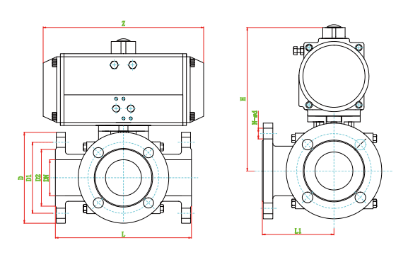
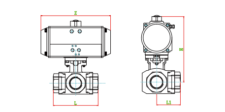
GB PN16 Main dimensions table (Unit: mm)
|
SIZE |
L |
L1 |
D2 |
D1 |
D |
N-ø d |
DA |
SR |
||
|
H |
Z |
H |
Z |
|||||||
|
DN15 |
150 |
75 |
46 |
65 |
95 |
4-ø 14 |
150 |
147 |
170 |
168 |
|
DN20 |
160 |
80 |
56 |
75 |
105 |
4-ø 14 |
170 |
168 |
190 |
204 |
|
DN25 |
180 |
90 |
65 |
85 |
115 |
4-ø 14 |
190 |
184 |
210 |
262 |
|
DN32 |
200 |
100 |
76 |
100 |
140 |
4-ø 18 |
210 |
204 |
235 |
268 |
|
DN40 |
220 |
110 |
84 |
110 |
150 |
4-ø 18 |
240 |
262 |
290 |
296 |
|
DN50 |
240 |
120 |
99 |
125 |
165 |
4-ø 18 |
270 |
268 |
315 |
390 |
|
DN65 |
260 |
130 |
118 |
145 |
185 |
8-ø 18 |
215 |
296 |
360 |
454 |
|
DN80 |
280 |
140 |
132 |
160 |
200 |
8-ø 18 |
390 |
454 |
420 |
525 |
|
DN100 |
320 |
160 |
156 |
180 |
220 |
8-ø 18 |
450 |
525 |
475 |
532 |
|
DN125 |
380 |
190 |
184 |
210 |
250 |
8-ø 18 |
500 |
532 |
530 |
610 |
|
DN150 |
440 |
220 |
211 |
240 |
285 |
8-ø 22 |
570 |
610 |
606 |
722 |
| DN200 | 550 | 275 | 266 | 295 | 340 | 12-ø 22 | 690 | 722 | 726 | 830 |
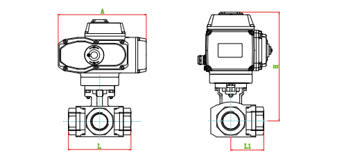
ELECTRIC THREE-WAY FLANGE BALL VALVE
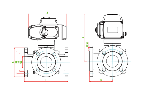
GB PN16 Main dimensions table (Unit: mm)
|
SIZE |
L |
L1 |
D2 |
D1 |
D |
N-ø d |
A |
H |
SIZE |
|
DN15 |
150 |
75 |
46 |
65 |
95 |
4-ø 14 |
165 |
200 |
SPD05 |
|
DN20 |
160 |
80 |
56 |
75 |
105 |
4-ø 14 |
165 |
210 |
SPD05 |
|
DN25 |
180 |
90 |
65 |
85 |
115 |
4-ø 14 |
212 |
240 |
SPD10 |
|
DN32 |
200 |
100 |
76 |
100 |
140 |
4-ø 18 |
212 |
250 |
SPD10 |
|
DN40 |
220 |
110 |
84 |
110 |
150 |
4-ø 18 |
259 |
310 |
SPD20 |
|
DN50 |
240 |
120 |
99 |
125 |
165 |
4-ø 18 |
259 |
320 |
SPD20 |
|
DN65 |
260 |
130 |
118 |
145 |
185 |
8-ø 18 |
259 |
335 |
SPD40 |
|
DN80 |
280 |
140 |
132 |
160 |
200 |
8-ø 18 |
259 |
365 |
SPD60 |
|
DN100 |
320 |
160 |
156 |
180 |
220 |
8-ø 18 |
284 |
420 |
SPD100 |
|
DN125 |
380 |
190 |
184 |
210 |
250 |
8-ø 18 |
284 |
440 |
SPD200 |
|
DN150 |
440 |
220 |
211 |
240 |
285 |
8-ø 22 |
284 |
470 |
SPD200 |
|
DN200 |
550 |
275 |
266 |
295 |
340 |
12-ø 22 |
500 |
700 |
SPD400 |
TEE THREAD BALL VALVE
|
Serial number |
Part Name |
material |
|
1 |
Body |
CF8, CF8M, CF3M |
|
2 |
Bonnet |
CF8, CF8M, CF3M |
|
3 |
Ball body |
SS304, SS316, SS316L |
|
4 |
Seat |
PTFE, PPL |
|
5 |
Stem |
SS304, SS316, SS316L |
|
6 |
Inverted seal |
PTFE, PPL |
|
7 |
O-ring |
VITON |
|
8 |
Filler |
PTFE, PPL |
|
9 |
Filling clamping ring |
SS304 |
|
10 |
Butterfly spring |
SS304 |
|
11 |
NUT |
SS304 |
|
12 |
Gland of valve |
CF8 |
|
13 |
Screw |
SS304 |
Product structure design feature
Valve stem anti-blowing structure design (see picture 1)
In valve stem anti-blowing structure design, the lower end is larger and the upper end is smaller Under the positioning of the upper-end cover and screws, even in the valve cavity is abnormal In this case, it can also ensure that the valve stem will not be blown out by the medium.
Anti-static design(See picture 2)
The fixed ball valve adopts an anti-static design to make the ball, stem and valve The body forms an electrostatic channel. So that the ball and the seat are switched During the process, static electricity generated by friction is led to the ground through the valve body, Preventing the risk of fire or explosion caused by static sparks.
KV rated
|
SIZE |
DN15 |
DN20 |
DN25 |
DN32 |
DN40 |
DN50 |
|
Kv |
13 |
21 |
38 |
72 |
112 |
170 |
Soft seal torque table (N.m)
|
SIZE |
DN15 |
DN20 |
DN25 |
DN32 |
DN40 |
DN50 |
|
PN16 |
4 |
6 |
10 |
20 |
26 |
32 |
|
PN25 |
7 |
10 |
14 |
22 |
30 |
36 |
|
PN40 |
11 |
14 |
20 |
48 |
60 |
70 |
|
PN63 |
16 |
30 |
60 |
100 |
130 |
160 |
|
SIZE |
D |
L |
L1 |
H |
M |
P |
J |
K |
R |
S |
|
|
DN15 |
1/2″ |
12 |
79 |
39.5 |
48.5 |
10 |
9 |
42 |
50 |
6 |
7 |
|
DN20 |
3/4″ |
16 |
86 |
43 |
53.5 |
10 |
9 |
42 |
50 |
6 |
7 |
|
DN25 |
1″ |
20 |
101 |
50.5 |
60 |
13 |
11 |
42 |
50 |
6 |
7 |
|
DN32 |
1-1/4″ |
25 |
114 |
57 |
67.5 |
13 |
11 |
42 |
50 |
6 |
7 |
|
DN40 |
1-1/2″ |
32 |
136 |
68 |
74 |
16 |
14 |
50 |
70 |
7 |
9 |
|
DN50 |
2″ |
38 |
152 |
76 |
82.5 |
16 |
14 |
50 |
70 |
7 |
9 |
PNEUMATIC/ELECTRIC TEE THREAD BALL VALVE
1000 WOG Main dimensions table (Unit: mm)
|
SIZE |
L |
L1 |
DA |
SR |
|||
|
H |
Z |
H |
Z |
||||
|
DN15 |
1/2″ |
75 |
37.5 |
135 |
147 |
150 |
168 |
|
DN20 |
3/4″ |
85 |
42.5 |
160 |
168 |
170 |
184 |
|
DN25 |
1″ |
100 |
50 |
180 |
184 |
190 |
204 |
|
DN32 |
1-1/4″ |
115 |
57.5 |
190 |
204 |
200 |
262 |
|
DN40 |
1-1/2″ |
124 |
62 |
210 |
262 |
225 |
268 |
|
DN50 |
2″ |
147 |
75 |
230 |
268 |
265 |
296 |
1000 WOG Main dimensions table (Unit: mm)
|
SIZE |
L |
L1 |
A |
H |
|
|
DN15 |
1/2″ |
75 |
37.5 |
165 |
180 |
|
DN20 |
3/4″ |
85 |
42.5 |
165 |
190 |
|
DN25 |
1″ |
100 |
50 |
165 |
230 |
|
DN32 |
1-1/4″ |
115 |
57.5 |
212 |
240 |
|
DN40 |
1-1/2″ |
124 |
62 |
212 |
275 |
|
DN50 |
2″ |
147 |
75 |
259 |
285 |


