L Type Three-Way Ball Valves for Natural Gas Reversing in Glass Melting Furnaces
Sep 09, 2025
Abstract: This study examines the use of a single "L"-type three-way ball valve in the reversing unit of a pair of small furnaces, replacing the two straight-through ball valves traditionally employed as actuators for natural gas reversing combustion in glass melting furnaces.
In the routine production of large and medium-sized float glass, reversing combustion is commonly used, with burners on both sides igniting alternately at fixed intervals. Domestic production lines for high-quality float glass typically use natural gas as fuel, which is delivered to the burners in the small furnaces through pipelines. The burners are ignited alternately by periodically opening and closing two-way valves in the control pipelines, thereby achieving reversing combustion. The clean quality of natural gas also allows the use of precision-machined control valves in the reversing combustion actuator. This paper analyzes the types and structures of three-way ball valves, along with the valve group configuration of the natural gas reversing chamber under a typical design scheme, to assess the feasibility of using an "L"-type three-way ball valve as the main valve for the reversing combustion actuator in glass melting furnaces.

Figure 1 Schematic diagram of the basic flow path state of the "T" type three-way ball valve
In general, there is no external difference between "T"-type and "L"-type three-way ball valves. The distinction lies in the valve core, which comes in two designs: three-way ("T") and right-angle ("L"). Each type has distinct functional characteristics. The "L"-type valve is generally used for distribution and switching where a three-way connection is not required. It is easy to operate, featuring two valve positions and a detent, and requires only a 90° rotation. The "T"-type valve offers a wider range of flow options and valve positions but typically lacks a detent, allowing operation at angles ranging from 90° to 360°. Both "T"- and "L"-type three-way ball valves employ a four-sided seat design, which balances forces and ensures reliable sealing of the closed channels. The "L"-type valve is mainly used for flow reversing, whereas the "T"-type valve is primarily used for flow diversion, mixing, reversing, and fully opening all three channels. In a glass melting furnace, the fuel supply flow path for each pair of small furnaces is split into two within the reversing control chamber. The Distributed Control System (DCS) manages the valves in these flow paths, alternately opening and closing them. This arrangement ensures a continuous and balanced fuel supply to the burners on opposite sides of the furnaces, achieving reversing combustion through alternating burner ignition.

Figure 2: Basic flow path of an "L"-type three-way ball valve
To achieve reversing combustion of natural gas, a reversing control room is typically located near the furnace end of the production line. Currently, the natural gas reversing control room for large float glass melting furnaces is configured as an indoor, spread-out installation. Various valves and equipment, including reversing valves, are interconnected on-site using pipes and fittings. Independent combustion reversing control systems are implemented according to the number of small furnaces in the unit. The core of each pair of small furnaces’ combustion reversing control system comprises two sets of valves that regulate the opening and closing of the pipelines. These valves are periodically operated by the production line’s Distributed Control System (DCS). The control flow is shown in Figure 3.
")
Figure 3. Process flow of the reversing control unit (general design)
4. Feasibility of Using an L-Type Three-Way Ball Valve as the Actuator for Natural Gas Reversing Combustion
In a glass melting furnace with dual-sided natural gas burners operating in alternating combustion, the core function of reversing control is to use valves to cut off, distribute, and redirect the gas within the pipeline, enabling natural gas to be discharged alternately and regularly through the two pipelines. Accordingly, a three-way, four-sided seated ball valve with a simple L-shaped flow path can serve as the main valve for the reversing actuator in the natural gas reversing chamber of a glass melting furnace. As shown in Figure 4, the orthogonal port of the three-way valve serves as the natural gas inlet (1), while the two horizontal ports (2 and 3) serve as the natural gas outlets. By rotating the three-way valve’s L-shaped core 90° clockwise or counterclockwise, one outlet pipeline is opened while the other is simultaneously closed.
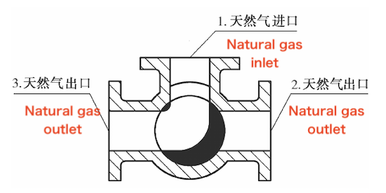
Figure 4
Operating Principle
The operating principle is as follows:
Opening Process:
① In the closed position, the ball is firmly pressed against the valve seat by the mechanical force of the valve stem.
② When the actuator rotates counterclockwise, the valve stem rises, and the angled flat surface at its lower end disengages the ball from the valve seat.
③ As the valve stem continues to rise, it engages the guide pin in the spiral groove, causing the ball to rotate without friction.
④ When the valve stem reaches its upper limit, the ball attains the fully open position.
Closing Process:
① To close, the actuator rotates clockwise, causing the valve stem to descend, which disengages the ball from the valve seat and initiates its rotation.
② As the handwheel continues to turn, the valve stem, interacting with the guide pin in the spiral groove, simultaneously rotates both the stem and the ball by 90°.
③ As the valve nears the closed position, the ball has already completed its 90° rotation without contacting the valve seat.
④ During the final turns of the handwheel, the angled plane at the bottom of the valve stem mechanically wedges the ball against the valve seat, achieving a tight seal.
The control process is shown in Figure 5.
")
Figure 5. Process flow of the reversing control unit (using the design of the “I”-type three-way ball valve)
The L-type three-way ball valve has a unique structural design, compact size, and lightweight construction. Its primary advantages include:
Frictionless opening and closing: This completely eliminates the reduction in sealing performance caused by friction between the sealing surfaces in traditional valves.
Top-mounted structure: Valves installed on pipelines can be directly inspected and serviced online, minimizing downtime and reducing maintenance costs.
Single-seat design: This eliminates safety risks associated with abnormal pressure increases within the valve cavity.
Low-torque design: A specially designed valve stem allows the valve to be easily opened and closed using a low-power actuator.
Wedge-shaped sealing structure: The valve is sealed by the mechanical force of the stem, which presses the ball firmly into the valve seat. This ensures reliable sealing performance regardless of pipeline pressure fluctuations and under various operating conditions.
Self-cleaning sealing surface: When the ball tilts away from the valve seat, the pipeline fluid flows evenly across the entire 360° sealing surface. This prevents localized erosion of the seat by high-velocity flow and simultaneously removes deposits, providing an effective self-cleaning function.
The three-way ball valve can be fitted with either a multi-turn electric actuator or a pneumatic actuator to achieve precise control of natural gas pipelines. With the support of a specially designed control system, it is fully capable of executing the reversing control function in the natural gas reversing chamber of glass melting furnaces. Once implemented, this solution can reduce the number of valves needed in a project, minimize control nodes in the Distributed Control System (DCS), allow for a more compact design, and directly lower both construction costs and space requirements. Furthermore, it significantly reduces maintenance demands during subsequent operation.
Previous: Design of a Split-Compensating Ball Valve
Next: Optimized Design and Performance of Electric Gate Valves for Nuclear Power Plants


