Structural Design Optimization of Ultra-High-Pressure Ball Valves
Aug 08, 2025
Abstract: This article details the structural design optimization of a domestically produced ultra-high-pressure (UHP) ball valve utilized in a national oil and gas field project. It outlines the critical functions and significance of ultra-high-pressure (UHP) ball valves within the oil and gas industry. Building on conventional design principles, this paper proposes a series of optimization solutions targeting key components, including ball support and positioning, seat sealing surfaces, stem-to-ball connection, transmission chain parameters, media erosion resistance, body strength and minimum wall thickness, as well as body-cover sealing. These improvements ensure reliable sealing performance, smooth and flexible operation, and jam-free functionality under ultra-high-pressure conditions. The optimized design improves valve safety and operational stability, serving as a valuable reference for the structural design of ultra-high-pressure ball valves in projects such as the Gouyou gas field.
Ball valves are widely used in industrial pipeline systems due to their excellent sealing capability, low flow resistance, compact structure, flexible operation, high safety, and long service life. Among these, ultra-high-pressure ball valves are especially critical for onshore wellheads and offshore platform wellhead facilities, serving as key components in the production process. These valves are responsible for opening and closing pipelines, controlling flow direction, and regulating the transported medium. They provide rapid shut-off capabilities and serve as core control devices for managing oil and gas flow and maintaining stable pressure. In secondary injection and pressure recovery operations, they are often referred to as the "throat" of gas field transportation systems. This paper proposes structural design optimizations for ultra-high-pressure (UHP) ball valves, focusing on several critical areas: ball support and positioning, valve seat sealing surfaces, stem-to-ball connection, transmission chain parameters, erosion resistance, housing strength and wall thickness, and body-cover sealing. The aim is to enhance the valve’s overall performance while ensuring safe and stable operation under ultra-high-pressure conditions.
Using a domestic gas field project as a case study, Table 1 lists the main technical parameters of the ultra-high-pressure ball valve.
The ball support structure should be designed with upper and lower support plates, as illustrated in Figure 1. Two symmetrical support plates are mounted on the ball. When the valve seats are installed into the seat cavities of the left and right valve body sections, their centers align precisely with the centers of the respective valve bodies. Once the support plates are properly fitted to the left and right valve bodies, their centers align as well. When the middle valve body is correctly assembled with the left and right sections, its center also aligns with theirs. As a result, the centers of the valve seats, support plates, and middle valve body are all aligned along the axis defined by the flow passages of the left and right valve bodies. This precise alignment ensures accurate positioning of the ball, resulting in a consistently tight seal between the ball and the seats. This leads to smooth valve operation, reduced operating torque, and a significantly extended service life. Whenever possible, vertical shaft support structures should be avoided, as they function as cantilever beams and are prone to elastic deformation under ultra-high-pressure loads. During valve operation, these vertical shafts are subjected to combined bending and torsional stresses, which may lead to ball misalignment, increased opening torque, and even operational failure.
Table 1. Ultra-High-Pressure Ball Valve Technical Parameters
|
Parameter |
Specification |
|
Diameter |
NPS 1" to 13 1/8" |
|
Pressure Rating |
10,000 psi |
|
Design Standard |
API 6A 151 |
|
Body Material |
A182 F51 |
|
Seal Material |
TCC |
|
Performance Level |
PR2 |
|
Specification Level |
PSL3G |
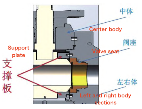
Figure 1 Ball Support Structure
The valve seat sealing surface should incorporate an elastic groove structure, as illustrated in Figure 2. Traditional high-pressure ball valve sealing surfaces typically feature either wide bevels or spherical profiles. Under high pressure, these surfaces tend to deform outward and warp, leading to uneven stress distribution on the sealing surface coating, which may result in cracking in severe cases. In contrast, the elastic groove structure transforms slight deformations of the sealing surface into bending of the base material, allowing the entire sealing area to deform uniformly. This prevents cracking caused by uneven warping and ensures reliable sealing performance. Finite element analysis was conducted on both the conventional and elastic groove valve seat designs. The geometric dimensions of the two seat structures were identical, except for the localized geometry of the sealing surface. Both designs were made from the same material, and the medium pressure was set to 10,000 psi (69 MPa). The simulation results are shown in Figure 3. When comparing the stress loads on the two structures, the elastic groove valve seat design exhibits significantly lower stress than the conventional valve seat design.
The connection between the valve stem and the ball should use a close-fitting involute spline, square head, or hexagonal head structure, as illustrated in Figures 4 and 5, respectively. These three structures significantly increase the contact area, while the multi-faceted contact helps distribute stress concentrations. The involute spline and square head mating structures notably enhance torque-carrying capacity and impact resistance. The square head structure is ideal for small-diameter ultra-high-pressure valves, whereas the hexagonal head and involute spline structures are better suited for medium- and large-diameter ultra-high-pressure valves. Additionally, flat square structures should be avoided because they can create excessive clearance between the stem and ball, which is difficult to eliminate. This issue is especially problematic in ESD ultra-high-pressure valves, where the local contact surface experiences a strong, instantaneous impact upon closing. Excessive clearance can cause stem deflection, significantly compromising structural stability. Furthermore, the stem material should be high-strength ASTM B637 NO77188, with the key made of 17-4PH stainless steel. Parameter requirements are listed in Table 2.
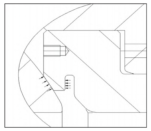
Figure 2 Valve Seat Elastic Groove Structure
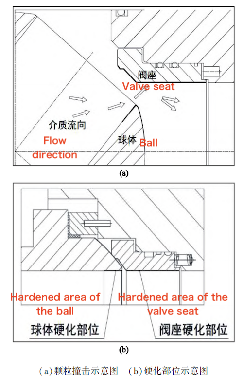
As shown in Figure 6, the anti-media erosion structure forms a narrow gap between the ball and seat seal during the initial opening and final closing phases of the ball valve, resulting in ultra-high-speed flow. When the medium contains solid particles, these particles combine with the ultra-high-speed gas flow to form a gas-solid two-phase mixture. The solid particles in this mixture carry significant kinetic energy during high-speed flow and frequently impact the ball orifice and seat bore, causing micro-cutting wear. Over time, this can easily lead to wear or scratches on the ball orifice and may even cause perforation of the valve seat. Therefore, both the ball orifice and the inner bore of the valve seat must be hardened. If necessary, the ball orifice should also incorporate an anti-scouring structure to withstand the impact and erosion caused by the medium when the valve opens from 0% to 10%.
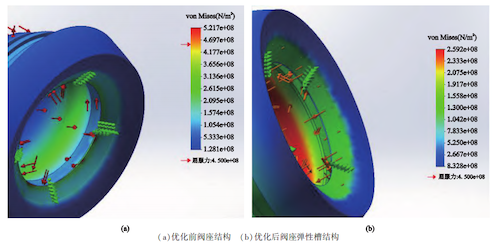
Figure 3 Valve Seat Sealing Surface Structure
(a) Valve Seat Structure Before Optimization (b) Valve Seat Elastic Groove Structure After Optimization
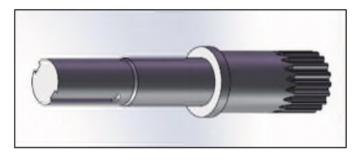
Figure 4 Spline Structure
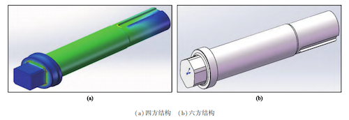
Figure 5 Transmission Mating Structures
(a) Square Head Structure (b) Hexagonal Head Structure
Table 2 Material parameters
|
Material |
Tensile strength (MPa) |
Yield strength (MPa) |
Hardness (HRC) |
|
17-4PH |
860 |
725 |
24–33 |
|
N07718 |
1034 |
827 |
35–40 |
The minimum wall thickness and strength design of the shell must be distinguished from those of the API 6D high-pressure ball valve. The minimum wall thickness for the API 6D ball valve is based on ASME B16.34 Table 3A; however, this standard does not cover pressures as high as 10,000 psi (69 MPa). Therefore, in addition to following ASME BPVC, the formula for the minimum wall thickness of a cylinder under internal pressure, as specified in section VII.2-2023, must also be applied. Since the shell wall thickness is reduced by the axial and vertical openings, and both end stress and torque loads are applied, the valve body’s equivalent stress verification should be performed in accordance with API 6X Design Calculations for Pressure-Containing Equipment (see Figure 7).
The formulas for calculating the minimum shell wall thickness and equivalent stress are as follows:

Where:
t = minimum shell wall thickness (mm)
D = inner diameter of the shell (mm)
P = design pressure (MPa)
S = allowable stress at the design temperature (MPa)
E = joint efficiency coefficient

Where:
Seq = equivalent stress (MPa)
1. Center body 2. Left and right bodies 3. Pressure-sealing metal gasket 4. Pressure-sealing ring 5. Inner seal ring 6. Outer seal ring 7. Wedge-shaped support ring
8. Spring
(a) Sealing structure between body and cover (b) Primary seal
Figure 6 Anti-media scour structure
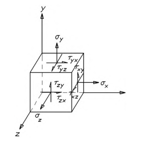
Figure 7: Stress component diagram
The body-cover sealing structure should incorporate a pressure-sealing design with two static seals: a primary seal and a secondary seal. The primary seal consists of two polymer sealing materials with different hardness values, while the secondary seal employs two metals of varying hardness. This combination of materials with differing hardness creates a mechanical interlocking seal that effectively prevents leakage under high-pressure gas conditions. Fluororubber O-rings or metal spiral wound gaskets should be avoided whenever possible. Fluororubber O-rings tend to lose elasticity gradually due to stress relaxation under prolonged high-pressure conditions, and ultra-high pressures accelerate this irreversible deformation. Additionally, fluororubber O-rings can easily be forced into sealing gaps, causing edge scratches or structural tearing. The graphite sealing tape used in metal spiral wound gaskets is somewhat porous, which poses a risk to sealing reliability under high-pressure gas conditions.
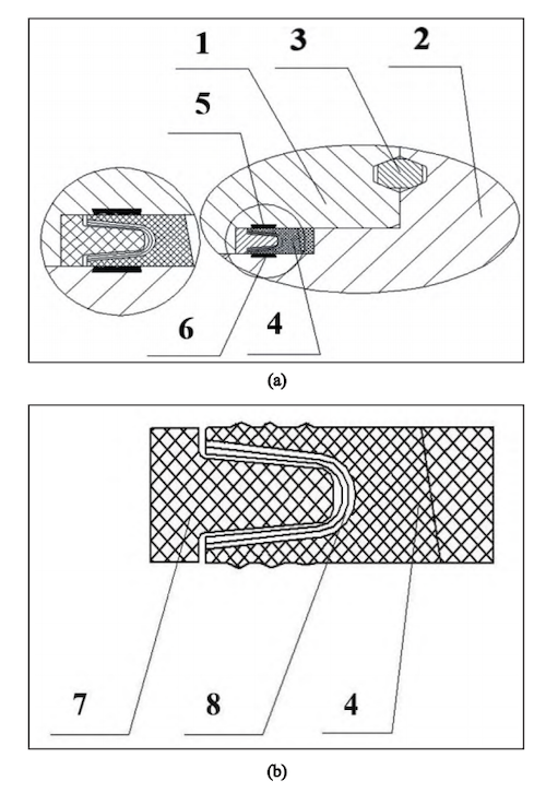
1. Center body 2. Left and right bodies 3. Pressure-sealing metal gasket 4. Pressure-sealing ring 5. Inner seal ring 6. Outer seal ring 7. Wedge-shaped support ring 8. Spring
(a) Body-cover sealing structure (b) Primary seal
Figure 8 Body-cover sealing structure
The design of the rapid leak detection structure and early warning device is shown in Figure 9. Installing a pressure sensor at the leak detection port enables online monitoring, thereby enhancing valve safety. Testing API 6A PSL 3G 10,000 psi high-pressure products carries significant risk, and the pressure buildup process is relatively slow. To ensure safety and improve production efficiency, a leak detection port is installed between the pressure-sealing metal gasket and the pressure-sealing ring within the body-cover seal. After valve assembly, because the integrity of the pressure-sealing ring and the pressure-sealing metal gasket cannot be visually verified, the leak detection port between the seals enables verification of the sealing performance of both components. High-pressure gas is introduced through the leak detection port, and changes in pressure or the presence of bubbles quickly reveal the integrity of the housing seal. This setup not only enables rapid leak detection but also reduces the time needed for valve assembly and pressure testing, thereby improving work efficiency and minimizing risks during the testing process. During valve operation, a pressure sensor installed at the rapid leak detection port provides an immediate alarm upon leakage, further enhancing production safety.
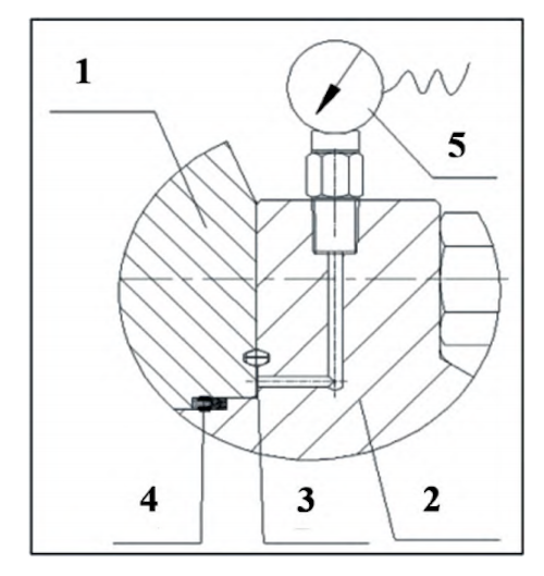
1. Valve body 2. Valve bonnet 3. Pressure-sealing metal gasket 4. Pressure-sealing ring 5. Pressure sensor
Figure 9: Rapid Leak Detection Structure and Warning Device
This article provides a detailed analysis of ultra-high-pressure ball valves, including the selection of ball support and positioning structures, force analysis of the seat sealing surface, comparison of stem-to-ball connection designs, parameter requirements for the transmission chain, the role of media erosion prevention technology, recommended calculation formulas for shell strength and minimum wall thickness, and the design of body and cover sealing structures. The optimized design has been mass-produced, with product performance tested and approved according to API 6A PSL 3G standards. Key technical parameters and performance indicators have reached an advanced level compared to similar international products. The optimized valve has been mass-produced for a domestic atmospheric gas field project with a capacity of 100 billion cubic meters, breaking the long-standing monopoly of foreign ultra-high-pressure ball valves and replacing imported products. This achievement is a significant milestone in the localization process. Future research will utilize ANSYS to optimize vibration and noise reduction technologies by analyzing the fluid-solid coupling vibration modes, frequencies, and overall vibration levels of the valve at various openings, enabling quantitative evaluation of its vibration characteristics. Additionally, sound propagation and radiation caused by supersonic fluid flow will be analyzed based on supersonic unsteady flow boundary conditions and boundary layer coherent structures, aiming to reveal the mechanisms by which supersonic mixed waveforms influence vibration and noise. This research will support the development of design methods for ultra-high-pressure ball valve vibration and noise reduction, utilizing both active and passive suppression techniques.
Previous: Water Pressure Management Valves: Performance and Use
Next: Optimizing DLC Coatings for Hardness and Low Friction on Nuclear Valve Stems
