Optimized Valve Selection for Offshore Chemical Flooding Surface Facilities
May 29, 2025
Valves are critical components in the pipeline systems of offshore oilfield chemical flooding surface facilities. Their selection directly impacts the operational performance of chemical flooding processes. Due to the limited application of chemical flooding in offshore oilfields, there is a lack of experience in selecting suitable valves. This paper analyzes valve types, materials, and connection methods, and provides a detailed approach to process valve selection.
Chemical flooding is a tertiary oil recovery method that enhances recovery efficiency by injecting polymer solutions. The surface facilities of such operations require accurate and reliable delivery of chemical agents through pipelines, making valve performance crucial for the safe and stable operation of the system. The harsh offshore environment and variations in fluid media introduce specific challenges and requirements for valve selection. Appropriate valve selection is essential for ensuring operational safety, controlling costs, and improving economic efficiency.
Valves are used to control the direction, flow rate, and pressure of fluids within pipelines. Their primary functions include flow shutoff, backflow prevention, flow regulation, and pressure relief. Based on actuation methods, valves can be categorized as manual, pneumatic, hydraulic, or electric. Common valve types used in offshore chemical flooding surface systems include butterfly valves, gate valves, ball valves, check valves, globe valves, and flow control valves.
A butterfly valve features a disc-shaped closure element that rotates around a fixed axis within the valve body to open or close the flow path. It is known for its simple structure, compact size, light weight, quick operation, and limited flow regulation capabilities. However, it is prone to internal leakage and has relatively low mechanical strength. Due to the limitations of soft-seated materials and structural integrity, butterfly valves in offshore oilfield chemical flooding surface facilities are typically reserved for low-pressure, low-viscosity media and installations with space constraints. Their use is limited and generally confined to seawater, firewater, water injection, drainage, and similar systems.
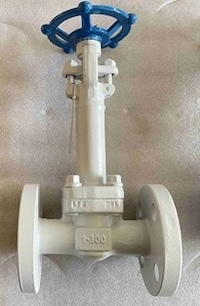
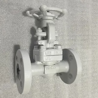
A gate valve utilizes a flat (or wedge-shaped) gate that moves perpendicular to the flow direction within the valve body. Turning the handwheel raises or lowers the gate to open or close the valve. Gate valves are valued for their excellent sealing performance, low fluid resistance, broad applicability, and moderate flow control capabilities. However, they are slow to operate, unsuitable for frequent cycling, and susceptible to water hammer. In offshore chemical flooding surface systems, gate valves are typically of the rising-stem type and are primarily used for high-point venting, low-point drainage, and isolation purposes. They represent approximately 20% of all valves used and are commonly installed for venting, sampling, and upstream of pressure gauges, differential pressure sensors, and other instrumentation.
Ball valves feature a spherical closure element with a central bore, which controls flow by rotating the ball. They are characterized by a simple structure, compact size, light weight, quick operation, low fluid resistance, and excellent sealing performance. However, they are relatively expensive and not suitable for flow regulation. In offshore oilfield chemical flooding surface systems, ball valves are ideal for high-viscosity media and applications requiring rapid opening and closing. They account for more than 50% of all valves used and are commonly applied in high-pressure water injection, polymer injection, produced water treatment, discharge, and fuel gas systems.
Check valves are automatic valves designed to prevent backflow. Inside the valve body is a swing disc or piston. When the flow direction of the medium aligns with the arrow marked on the valve body, the valve opens under fluid pressure. If the medium reverses direction, the disc or piston automatically closes—either by gravity or spring force—preventing reverse flow. Check valves are primarily used in locations where backflow prevention is critical. In offshore chemical flooding surface systems, they make up about 10% of all valves and are commonly used in water injection manifolds, polymer injection manifolds, pump outlets, and produced water systems.
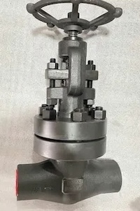
The globe valve uses a plug-shaped valve disc as its closing element, with a conical or flat sealing surface and a valve seat positioned perpendicular to the fluid flow direction. The valve disc moves linearly along the centerline of the flow. Due to its design, solids tend to settle on the valve seat, which can affect sealing performance. Therefore, globe valves are generally not recommended for fluids containing suspended solids but are well-suited for flow regulation. In offshore oilfield chemical flooding surface systems, globe valves account for about 10% of total valves, mainly used in water injection manifolds, bypass pipelines, polymer injection, produced water, and other systems requiring flow control.
Flow control valves come in various types and are generally categorized as self-operated or manually, pneumatically, or electrically actuated valves. They regulate and control fluid flow by adjusting the size of the flow passage within the valve. Self-operated flow control valves use the medium’s own pressure changes to achieve automatic flow regulation and are occasionally used on offshore platforms. In offshore oilfield chemical flooding surface systems, flow control valves are typically used for regulating high-pressure water injection and polymer solution flow. They are usually installed on water injection manifolds or at each branch of the polymer injection manifold, downstream of the water injection or polymer injection pumps, to precisely control the target fluid for polymer injection.
Valve selection for offshore oilfield chemical flooding surface systems is based on a comprehensive evaluation of valve function, material, connection method, size, operating temperature and pressure, fluid properties, and flow resistance. Selection is made with consideration of process conditions, safety and reliability, operation and maintenance requirements, and cost-effectiveness. This section outlines the principles of selecting valve types, materials, and end connections.
The first step in valve selection is determining the appropriate valve type. Only after the type is confirmed can further specifications be finalized. Valve type should be chosen based on process requirements, medium characteristics, operating conditions, and specific performance needs of the valve.
When selecting a valve, its intended function within the process must be clearly defined—whether it is for isolation, quick shut-off, or flow regulation—as well as the required leakage performance. Different valve types are suited to specific functions and operating conditions and should be selected accordingly.
Valves control the flow or shut-off of various process media. Each valve type offers different performance characteristics depending on the media involved. Offshore chemical flooding systems involve a wide range of media, requiring special attention during valve selection. For example, both the polymer mother liquor and the polymer injection target fluid have specific viscosity requirements, making valves that generate high shear forces unsuitable for these applications.
Valve selection must also consider operational and maintenance needs at each installation point. Space is limited on offshore platforms, making the physical footprint of valves a critical factor. In offshore chemical flooding surface systems, valve types should be selected based on process flow requirements, while also accommodating operational access and ease of maintenance. Valve placement and type should be clearly identified for each position in the piping and instrumentation diagram (P&ID).
Example: Water Injection Manifold Valve Selection
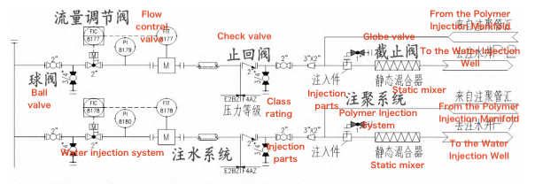
Figure 1 illustrates a portion of the water injection manifold process. High-pressure injection water is pumped to the manifold, where it mixes with polymer mother liquor from the polymer injection system. The combined stream is then thoroughly blended in a static mixer and injected into polymer wells.

Figure 1 Partial Process Flow of the Water Injection Manifold
To meet the viscosity and concentration requirements of the injection fluid, precise flow control is essential. Therefore, an electric flow control valve is used to regulate flow at this point. Because the injection water and polymer systems operate under different pressures, a check valve is installed before the polymer stream merges to prevent backflow. Each branch line includes a reserved cross-linking agent injection port, where a globe valve is used to control the dosage of injected chemicals.
In summary, valve type selection in chemical flooding surface systems is primarily driven by process requirements, with maintenance considerations playing a supporting role.
Once the valve type is selected based on process requirements, the next step is to determine the appropriate valve materials. To achieve a balance between cost-efficiency and durability, the valve body and its key components—typically the stem, disc (or ball), and seat—are often made from different materials. Material selection should consider factors such as the properties of the conveyed fluid, the valve’s operating environment, and the material of the connected piping.
Fluid Properties
The nature of the fluid plays a critical role in material selection. Whether the medium is a gas or a liquid, contains solid particles, or exhibits corrosive characteristics, all these factors influence the material requirements of the valve components.
Operating Environment
External factors like temperature, pressure, and exposure to corrosive atmospheres also affect material choice. For instance, bronze valves—commonly used on offshore platforms—typically handle temperatures up to around 250°C, while steel valves can withstand temperatures exceeding 400°C.
Connected Pipe Materials
The compatibility of the valve body material with the piping material is essential. Reactions such as carburization must be avoided at the interface to prevent premature failure and to extend the valve’s service life. In offshore oilfield chemical flooding surface systems, the operating environment and pipe material have relatively minor influence on valve material selection. Instead, the characteristics of the conveying medium are the primary consideration. These systems are typically subjected to humid and saline service conditions, with the maximum design temperature specified at approximately 200°C, which establishes fundamental material selection criteria for valves. The material selection for chemical flooding piping systems is restricted to carbon steel, stainless steel, or copper-nickel alloys to guarantee compatibility with injected chemicals and environmental conditions. However, with dozens of process systems and a wide range of media involved, material selection must account for the specific chemical and physical properties of each medium. Typical systems include:
Production and processing systems, such as those handling crude oil and associated gas, rely on a range of specialized subsystems to ensure safe and efficient operation. These include:
- Utility systems, which provide essential services such as fuel gas, instrument air, steam, diesel, seawater, and potable water
- Fire protection systems, which typically involve firewater networks and CO₂-based suppression systems
- Injection systems, which are used for water or polymer injection to maintain reservoir pressure and enhance oil recovery
Each medium presents distinct engineering challenges. For example, steam pipelines require materials capable of withstanding high temperatures; diesel lines must incorporate flame-resistant and explosion-proof features; seawater and firewater systems demand materials with excellent corrosion resistance; and water or polymer injection systems must operate reliably under high pressure.
The following provides an overview of typical ball valve material selection for various media:
- Instrument Gas Pipelines: These require excellent sealing performance. Valve bodies are typically made of stainless steel or WCB carbon steel, with stainless steel balls to ensure durability and corrosion resistance.
- Diesel Pipelines: As diesel is flammable and potentially explosive, valve bodies are usually made from forged carbon steel (A105), paired with stainless steel balls. These valves must comply with fire-safe and anti-static standards.
- Firewater Pipelines: Given the corrosive nature of seawater used in firewater systems, both the valve body and ball are typically made of nickel-aluminum bronze or Monel alloy to ensure long-term corrosion resistance.
The structure and size of a valve’s end connection play a critical role in its sealing performance and installation reliability. Improper selection may lead to installation issues or leakage during operation. Common end connection types include threaded, welded, and flanged connections, with flanged connections being the most widely used. In chemical flooding surface facilities, flanged connections are typically used for valves 2 inches and above, while valves smaller than 2 inches are usually threaded or welded, depending on pipeline material and process requirements.
The common flange facing types in chemical flooding applications include raised face (RF), flat face (FF), and ring-type joint (RTJ):
- FF (Flat Face) flanges are suitable for low-temperature, low-pressure environments and are commonly used with nickel-aluminum bronze valves.
- RTJ (Ring-Type Joint) flanges are preferred for high-temperature, high-pressure systems where superior sealing is required, and are typically used in Class 900 and above pipeline systems.
When selecting valves, factors such as size, pressure rating, and functional characteristics must be carefully considered and confirmed.
Valve size is generally determined by the fluid flow rate and the acceptable pressure drop. In chemical flooding surface engineering, valve sizes are usually matched to the corresponding process pipeline size. However, to reduce costs, valve sizes may be slightly reduced as long as they still meet the required specifications—for example, in high-pressure valves conforming to the API 6A standard.
Special functional requirements may also apply depending on the application or medium:
- Diesel pipeline valves must be fire-safe and anti-static.
- Steam pipeline valves must withstand high temperatures.
- Seawater and firewater valves should be lined with corrosion-resistant materials.
- Ball valves installed at safety valve discharge points should include through-holes and locking mechanisms to ensure safe pressure relief.
While the general approach to valve selection has been outlined above, certain considerations in chemical flooding surface engineering require special attention:
- Swing check valves rely on the pressure of the flowing medium to operate effectively. They should be installed horizontally, and must not be installed on vertical pipelines with downward flow, as this may prevent proper functioning.
- For polymer mother liquid and wellhead target liquid sampling, the standard combination of gate valve or ball valve with a needle valve is typically avoided. Instead, piston-type polymer samplers are used to ensure more reliable and consistent sampling.
- Valves on the main firewater ring network, as well as ball valves at safety valve discharge points, generally require lock-open devices in accordance with standard specifications, to prevent accidental closure during emergency conditions.
- Flow control valves are primarily used for high-pressure water injection and for regulating the distribution of polymer mother liquid. For high-pressure water injection, globe valves with electric actuators are commonly used.
Given the high viscosity of the polymer mother liquid and the need to minimize shear-induced viscosity loss, electric low-shear control valves are preferred. These valves are typically designed with a special Venturi structure to reduce pressure loss while maintaining flow control performance.
In summary, valve selection for offshore oilfield chemical flooding surface facilities involves the following considerations:
- The valve type, size, temperature, and pressure rating are determined based on process requirements.
- The valve material is selected according to the characteristics of the medium within the pipeline system.
- The connection type is chosen based on pipeline material, pressure rating, and sealing requirements.
- Finally, any special functional requirements, such as fire-safe design, anti-corrosion lining, or lock-open devices, are determined based on process conditions and medium properties.
By systematically addressing these factors, engineers can ensure appropriate valve selection for reliable and safe operation of chemical flooding surface pipeline systems.
Previous: Localization and Performance Optimization of Pneumatic Track Ball Valves for Marine Engineering
Next: Performance and Design Optimization of Pneumatic Orbital Ball Valves in Harsh Marine Conditions


