How Stem Roughness Affects Valve Sealing
May 06, 2025
This study systematically analyzes the impact of valve stem surface roughness and packing type on sealing performance. By testing valve stems with varying roughness levels (Ra 0.2, Ra 0.4, Ra 0.8, Ra 1.6, Ra 3.2) in combination with four different types of packing, the effects on sealing, friction, and leakage rates in both globe valves and ball valves were evaluated. The results show that valve stem roughness significantly influences both sealing and friction performance. For globe valves, the lowest leakage rate was observed at a roughness of Ra 0.4 µm, while for ball valves, Ra 1.6 µm yielded the best sealing performance. Additionally, different packing types had varying effects on friction and leakage, with packing type G demonstrating the best overall performance across all indicators. The study concludes that valve stem roughness and packing type are critical factors in determining valve sealing efficiency, offering valuable data and theoretical guidance for valve design optimization. These findings have important practical implications for enhancing valve stability, extending service life, and improving overall equipment performance.
In modern industrial systems, valves are essential components for fluid control, and their performance is critical to the safety, reliability, and efficiency of the entire system. In industries such as aerospace, petrochemicals, and nuclear energy, the sealing performance of valves is a key indicator of their quality. Valve stem packing technology ensures reliable valve operation in high-pressure, high-temperature, or corrosive media environments by utilizing the compressibility of the sealing material and applying appropriate preload.
The surface roughness of the valve stem has a significant effect on the packing’s sealing performance. A rough valve stem surface can compromise the compressibility and sealing effectiveness of the packing, while also increasing friction and wear. This, in turn, affects the operational stability and sealing reliability of the valve. Increased or inconsistent friction raises the contact stress between valve components, accelerates packing wear, and may cause the valve stem to stick or become locked, thereby impairing valve actuation and control precision. In control valves specifically, excessive friction can lead to faster packing degradation and higher leakage rates, negatively impacting both safety and the efficiency of process control systems. Therefore, minimizing packing friction and leakage is essential to ensuring stable and reliable valve operation.
Currently, some studies have examined the influence of stem surface roughness on packing sealing performance. SOTOODEH K conducted a failure analysis of leakage in ball valve stem packing seals and identified several influencing factors, including stem and packing roughness, packing compression force, packing material and dimensions, lubrication, and stem installation method. However, most existing research focuses on a single type of packing or a limited roughness range, lacking a systematic and comprehensive analysis. While current findings suggest that leakage rate is related to stem roughness and packing friction, the specific mechanisms and effective solutions require further investigation. Moreover, the performance of different packing materials under varying stem roughness has not been thoroughly compared with sufficient data. Therefore, a systematic study is essential to fill this research gap and provide a scientific foundation for optimizing valve design. This study conducted a series of tests at room temperature and atmospheric pressure to explore the combined effects of different stem roughness levels and packing types on valve performance.
The test materials used in this study include valve stem samples with varying surface roughness and four different types of valve stem packing. The specific materials are as follows:
Valve stem samples from globe valves with different roughness levels (Ra 0.2, Ra 0.4, Ra 0.8, Ra 1.6, Ra 3.2) were used, as shown in Figure 1a. The globe valve stems were tested under reciprocating motion to evaluate their impact on packing performance.
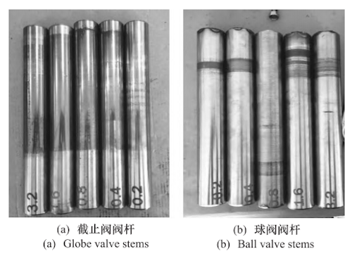
(a) Globe valve stem (b) Ball valve stem
Figure 1 Valve stem samples with different roughness
The ball valve stem samples with different roughness levels (Ra 0.2, Ra 0.4, Ra 0.8, Ra 1.6, Ra 3.2) are shown in Figure 1b. These samples were tested under 90° rotational motion to analyze the effect of stem roughness on the sealing performance and friction characteristics of ball valve packing.
(1) Packing Type A:
This structure consists of two layers of graphite braided packing with a V-shaped flexible graphite ring positioned in the middle, as shown in Figure 2. The upper and lower graphite braided packings are made of high-purity flexible graphite reinforced with stainless steel wire, formed through a molding process. They exhibit excellent resistance to high temperatures and chemical corrosion, effectively withstanding the effects of high pressure and aggressive media. The V-shaped flexible graphite ring in the middle fills the gap between the upper and lower packings to enhance overall sealing performance and improve the material’s flexibility and compressibility. This design combines the wear resistance of braided packing with the sealing efficiency of flexible graphite, making it suitable for valve applications that demand high sealing performance and long-term durability.
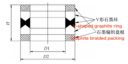
Figure 2 Packing Type A
(2) Packing Type B:
This packing material consists entirely of graphite braided packing. The graphite braided packing is made from high-purity flexible graphite reinforced with stainless steel wire and is formed through a molding process, as shown in Figure 3. It is known for its excellent wear resistance, high-temperature tolerance, and reliable sealing performance. This packing is well-suited for applications with demanding sealing requirements and offers strong durability and resistance to compression. The simplified structure of this design enables an efficient sealing effect using a single type of braided packing.
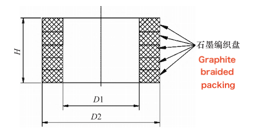
Figure 3 Packing Type B
(3) Packing Type C
This type consists of a packing ring with a rectangular cross-section, woven from specially treated high-carbon fiber, as shown in Figure 4. The base material is high-carbon fiber impregnated with graphite, which provides excellent strength and wear resistance. The graphite impregnation enhances lubricity and improves the packing’s resistance to high temperatures. The rectangular cross-section increases the sealing contact area, thereby improving the overall sealing performance. This structure offers outstanding sealing capability and a long service life, making it suitable for demanding high-pressure and high-temperature environments.
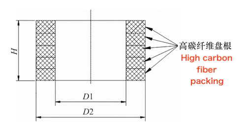
Figure 4 Packing Type C
(4) Packing Type D
This type combines upper and lower graphite braided packings with a flexible graphite ring of rectangular cross-section in the middle, as shown in Figure 5. The upper and lower braided packings are made from high-purity flexible graphite reinforced with stainless steel wire and formed through a molding process. They primarily serve to provide sealing and to prevent extrusion of the central graphite ring. The central rectangular flexible graphite ring performs the main sealing function, enhancing the material’s overall sealing performance and pressure resistance. This design maximizes the advantages of both braided packing and flexible graphite, improving sealing effectiveness and durability through a well-balanced structural combination.
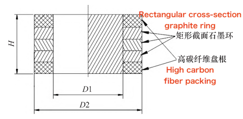
Figure 5 Packing Type D
This test uses hydrogen as the medium to evaluate the sealing leakage rate and friction performance of the valve stem packing. The main components of the test device include the gas source, valve body simulation, stuffing box, stuffing gland, valve stem, sealing cover, helium mass spectrometer leak detector, drive device, load sensor, sealing packing, and leakage and friction test device, as shown in Figure 6.
The core components of the test device are the stuffing box and the stuffing gland. The sealing packing is installed in the stuffing box and pre-tightened by the bolts of the stuffing gland to apply the necessary axial pressure for effective sealing. The valve stem is driven by the drive device to simulate the rotational motion of the valve stem relative to the packing under real operating conditions. During the test, the load sensor monitors the friction torque in real time. The entire test process is managed by a computer-controlled test machine, and the valve stem's movement mode can be adjusted according to different valve requirements, including linear motion or rotational motion. The test machine monitors the friction between the valve stem and the packing online in real time, and it also has the ability to adjust movement speed, rotation speed, and rotation angle to meet various test needs. The helium mass spectrometer leak detector is connected to the sealing cover, and the negative pressure vacuum detection method is used to detect helium leakage, ensuring the accurate evaluation of the packing sealing performance.
(1) Preparation Stage: Measure the inner diameter of the packing, the outer diameter of the valve stem, the inner and outer diameters of the packing gland, and the inner and outer diameters of the packing. Use a depth gauge to measure the depth of the stuffing box and the height of the packing gland boss to ensure accurate fit and installation of the packing. Select the appropriate valve stem roughness and packing type according to the test requirements, and confirm that all test materials and equipment are properly prepared.
(2) Packing Installation: Place the sealing packing onto the valve stem, ensuring it fits the dimensions of both the valve stem and the stuffing box. Install the packing gland onto the stuffing box and pre-tighten it using bolts. The pre-tightening force is calculated based on a specific surface sealing pressure of 35 MPa. Two M12 bolts are used, with each bolt tightened to a torque of 42.2 N·m. No spring washers are used during installation.
(3) Equipment Setup and Testing: Start the test machine and computer control system. Set the valve stem to perform linear reciprocating motion according to the test parameters, with a stroke length of 60 mm. Adjust the movement speed and stroke parameters to match real operating conditions. The test machine must be capable of recording friction and leakage values in real time during valve stem movement.
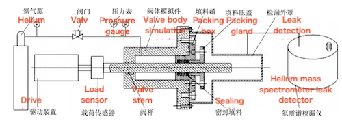
Figure 6 Leakage and Friction Test Device
(4) Leakage and Friction Test: Configure the test machine to perform reciprocating motion of the valve stem, set the stroke to 60 mm, and adjust the movement speed and frequency as required. Simultaneously, start the helium mass spectrometer leak detector and conduct negative pressure vacuum leak detection. At the beginning of the test, record the initial friction and leakage rate. Allow the valve stem to reciprocate and record the friction and leakage rate every 50 cycles. After completing 200 cycles, stop the test and record the residual torque of the packing gland.
(5) Data Recording and Analysis: After the test, power off the equipment and compile the test data, including friction, leakage rate, and the residual torque of the packing gland. Analyze the collected data to evaluate the impact of stem surface roughness on the performance of the globe valve.
2) Stem Packing Tests of Ball Valves
(1) Preparation Stage: Measure the inner diameter of the packing box, the outer diameter of the valve stem, and the inner and outer diameters of both the packing and the packing gland. Use a depth gauge to measure the depth of the packing box and the height of the packing gland boss to ensure accurate installation. Select the appropriate valve stem roughness and packing type, and confirm that all test materials and equipment are ready.
(2) Packing Installation: Install the sealing packing onto the valve stem, ensuring a proper fit with the stem diameter. Mount the packing gland and pre-tighten it using two M12 bolts, applying a torque of 29.7 N·m. Do not use spring washers during installation.
(3) Equipment Setup and Testing: Start the test machine and computer control system, and set the valve stem to perform a 90° rotational motion. Adjust the rotation speed and angle to simulate actual working conditions. Start the helium mass spectrometer leak detector and perform leak testing using the negative pressure vacuum method. Record the initial leakage rate.
(4) Friction Test: Set up the test equipment by configuring the machine to perform 90° rotations of the valve stem, adjusting the rotation speed and angle according to the test requirements. Start the test machine and the helium mass spectrometer leak detector, using the negative pressure vacuum method to verify proper sealing performance. At the beginning of the test, record the initial rotational torque and leakage rate. Then, conduct repeated 90° rotations of the valve stem, recording the torque and leakage rate every 50 rotations. After completing 200 rotations, stop the test and record the residual torque of the packing gland.
(5) Data Recording and Analysis: After completing the test, turn off the equipment and compile all recorded data. Analyze the torque, leakage rate, and residual torque of the packing gland under different roughness conditions to assess the impact of surface roughness on ball valve performance. Draw conclusions and summarize the findings.
Previous: Dynamic Water Closing Test of Ball Valve in High-Head Pumped Storage: Performance Analysis
Next: Impact of Valve Stem Surface Roughness on Packing Sealing Performance: Test Results and Analysis
